206 Rockwell Automation Publication 1766-UM001I-EN-P - June 2015
Appendix D Using ControlFLASH to Upgrade Your Operating System
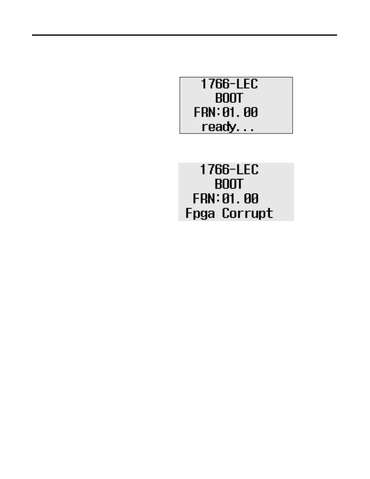
• The POWER LED is solid ON and the RUN, FAULT and FORCE LEDs
are blinking simultaneously. The LCD shows this information:
• The POWER and FAULT LED are solid ON and the LCD shows this
information:
When the LCD displays the Fpga Corrupt information, the LEDs do not
show the Walking pattern during the firmware upgrade process.
Recovering from Missing or Corrupt OS State
In order to recover from this controller state, you need to restart the operating
system firmware upgrade as described here:
1. Ensure that the Ethernet connections are intact.
SNMP is enabled by default in the controller.
2. If the IP Address was configured during the Preparing for firmware
upgrade stage, the same IP configuration is retained in the controller.
3. Start the Firmware upgrade as explained in Using ControlFLASH for
Firmware Upgrade on page 193.

 Loading...


