118 Rockwell Automation Publication 1766-UM001I-EN-P - June 2015
Chapter 5 Using the LCD
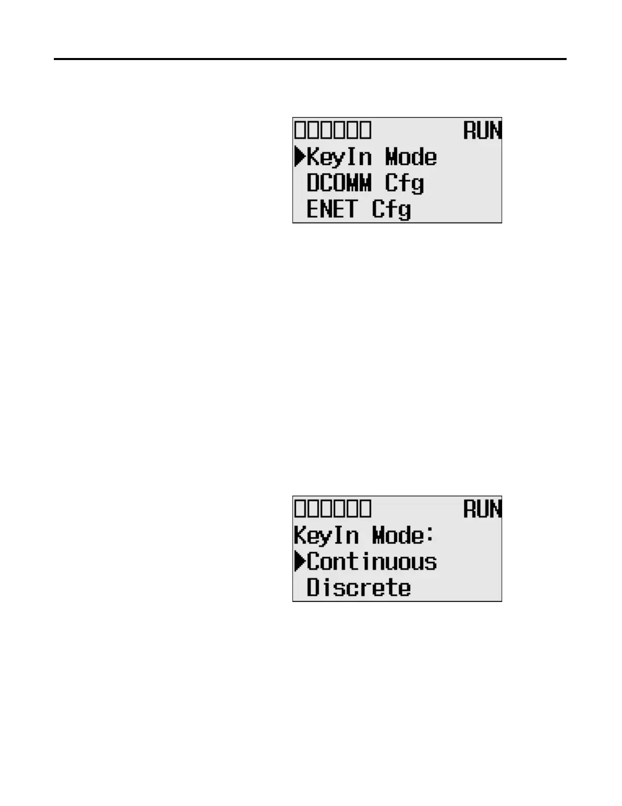
Changing Key In Mode
Key In Modes
There are two Key In modes, Continuous and Discrete.
The current Key In mode determines how the value changes are applied when
you press the Up and Down keys to change the data value for a trim pot. When
set to Continuous, the changes are applied immediately whenever you press the
Up and Down keys. When set to Discrete, the changes are applied only when you
press the OK key after you have changed the value using the Up and Down keys.
By using the Key In Mode screen, as shown below, you can change the Key In
mode to use.
Changing Key In Mode
Follow these steps to change the current Key In mode.
The Key In mode has an effect only when you change the data value
of a trim pot on a trim pot screen, either Trim Pot 0 or Trim Pot 1
screen. For more information on how to change the data value of a
trim pot, see Changing Data Value of a Trim Pot on page 132.

 Loading...


