Rockwell Automation Publication 1766-UM001I-EN-P - June 2015 63
Communication Connections Chapter 4
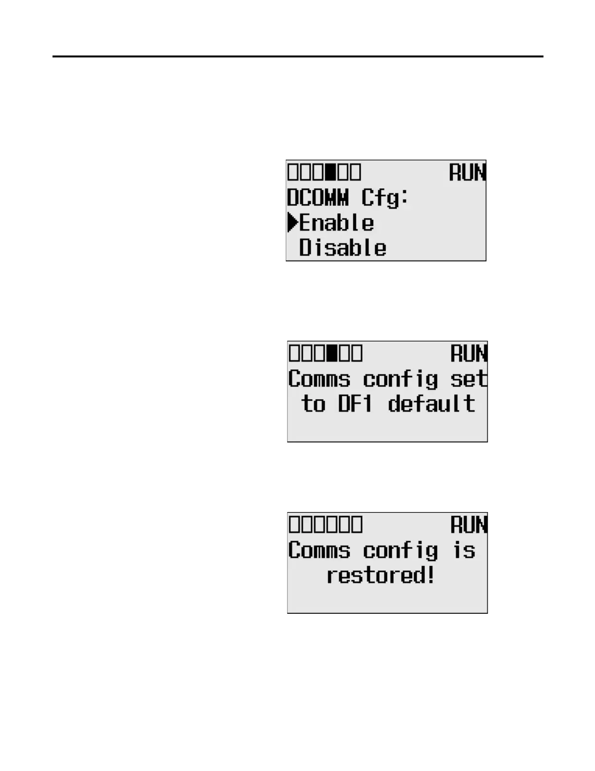
5. Use the up arrow to change the indicator position so that it is pointing to
Enable. Press the OK key to change to the default communication mode.
The DCOMM Mode Change Notification screen is displayed. It indicates
that the communication configuration is changed to the default
communication mode. The DCOMM status indicator is displayed in solid
rectangle.
If you change to the user-defined configuration from the default
configuration mode by selecting Disable and pressing the OK key, the
DCOMM Mode Change Notification will be displayed.
6. Press the ESC key to return to the Advanced Set Menu screen,
as shown in step 3.
Connecting to the RS-232
Port
There are two ways to connect the MicroLogix 1400 programmable controller to
your personal computer using the DF1 protocol: using a point-to-point
connection, or using a modem. Descriptions of these methods follow.
COM
M0
COM
M
1
D
COM
M
BA
T
.
LO
U-
DI
SP
COM
M
2

 Loading...


