Rockwell Automation Publication 1766-UM001I-EN-P - June 2015 183
Troubleshooting Your System Appendix C
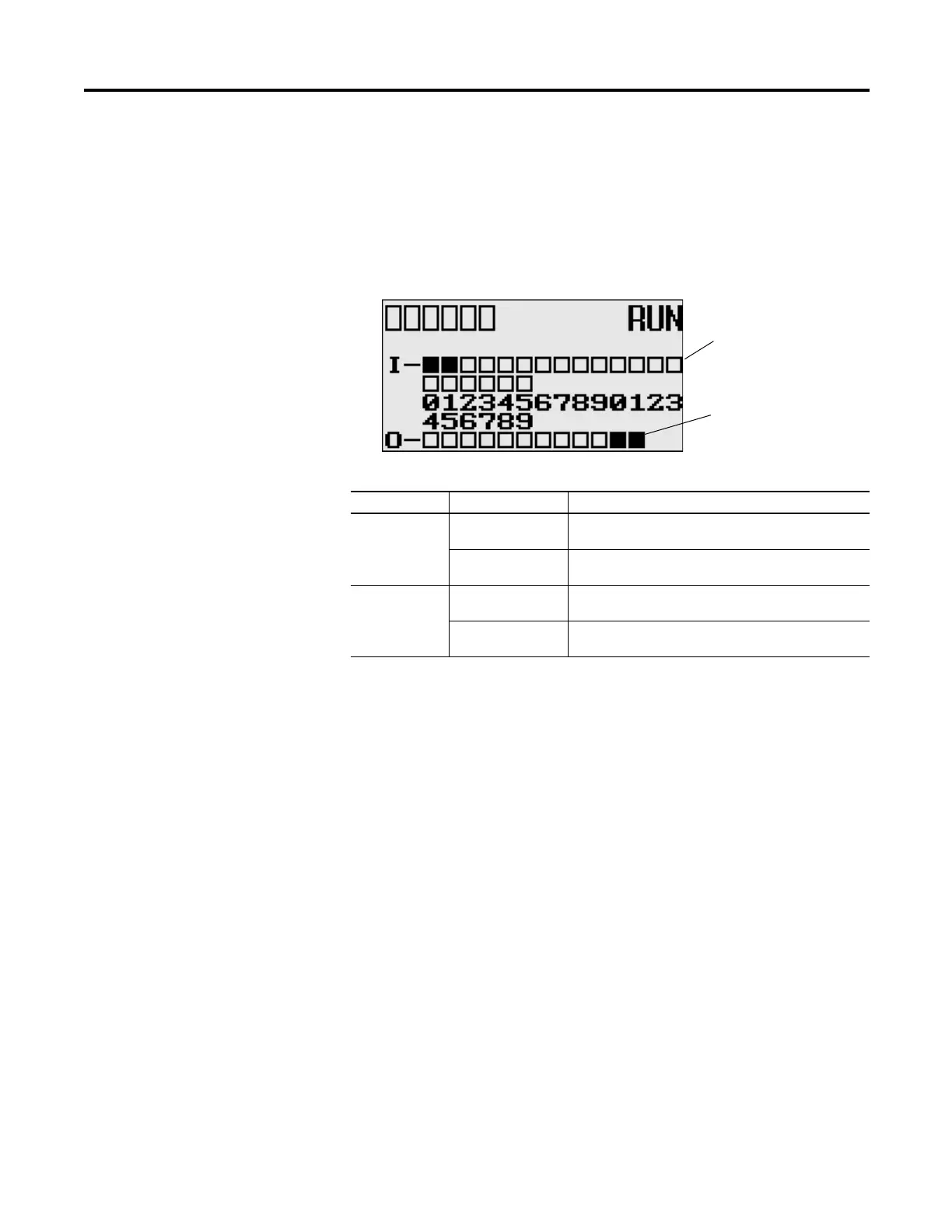
I/O Status Indicators on the LCD
Figure 5 - I/O Status Indicators on the LCD
Normal Operation
The POWER and RUN LEDs are On. If forcing is enabled and forces are
installed in I/O force files, the FORCE LED turns on and remains on until all
forces are removed. And if forcing is disabled and forces are installed in I/O force
files, the FORCE LED flashes and remains flashing until forces are removed from
I/O force files.
Error Conditions
If an error exists within the controller, the controller LEDs operate as described in
the following table.
(1)
When using a MicroLogix 1400 controller, the DCOMM LED applies only to Channel 0.
I/O Status Indicators on the LCD
Indicator Color Indicates
INPUTS
(1)
(1)
To view the status of inputs and outputs on the LCD, you need to enter the I/O LED mode screen using the LCD
menu. See I/O Status on page 5-93 for more information.
off
(empty rectangle)
Input is not energized
on
(solid rectangle)
Input is energized (terminal status)
OUTPUTS off
(empty rectangle)
Output is not energized
on
(solid rectangle)
Output is engerized (logic status)
Output status indicators (12)
Input status indicators (20)
I/O LED screen on the LCD

 Loading...


