36 Rockwell Automation Publication 1766-UM001I-EN-P - June 2015
Chapter 3 Wire Your Controller
Sinking and Sourcing
Wiring Diagrams
Any of the MicroLogix 1400 DC embedded input groups can be configured as
sinking or sourcing depending on how the DC COM is wired on the group.
1766-L32BWA, 1766-L32AWA, 1766-L32BXB, 1766-L32BWAA,
1766-L32AWAA, 1766-L32BXBA Wiring Diagrams
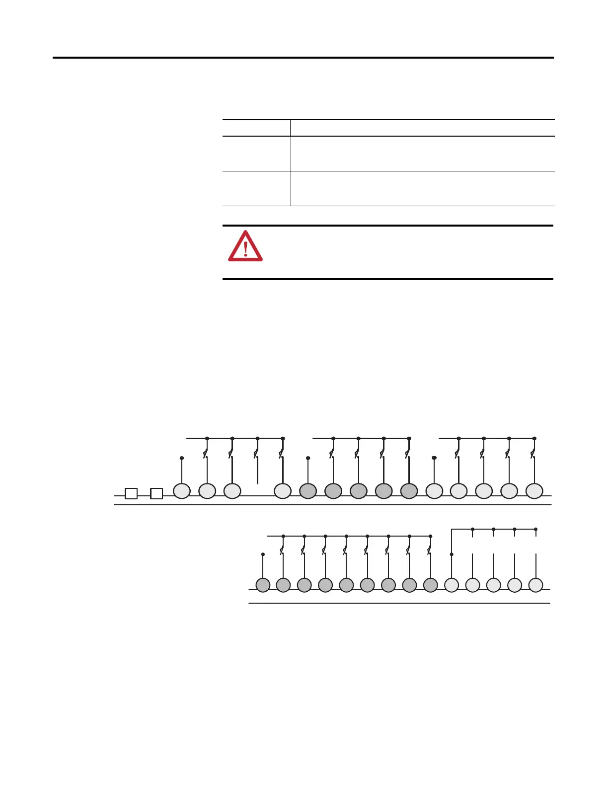
Figure 6 - 1766-L32AWA/L32AWAA Input Wiring Diagram
(1)
(1) “NOT USED” terminals are not intended for use as connection points.
Type Definition
Sinking Input The input energizes when high-level voltage is applied to the input terminal
(active high). Connect the power supply VDC (-) to the input group’s COM
terminal.
Sourcing Input The input energizes when low-level voltage is applied to the input terminal
(active low). Connect the power supply VDC (+) to the input group’s COM
terminal.
ATTENTION: The 24V DC sensor power source must not be used
to power output circuits. It should only be used to power input
devices (for example. sensors, switches). See Master Control Relay
on page 13 for information on MCR wiring in output circuits.
In the following diagrams, lower case alphabetic subscripts are
appended to common-terminal connections to indicate that different
power sources may be used for different isolated groups, if desired.
NOT
USED
NOT
USED
COM 0
L2a
L1a
IN0 IN1 IN2 IN3 COM 1
L2b
L1b
IN4 IN5 IN6 IN7 COM 2
L2c
L1c
IN8 IN9 IN10 IN11
COM 3
L2d
L1d
IN12 IN13 IN14 IN15
IN17 IN18 IN19IN16
COM
ANA
A
GND AIN0
IV0(+) IV1(+) IV2(+) IV3(+)
A
IN1 AIN2 AIN3
1766-L32AWAA only

 Loading...


