24 Rockwell Automation Publication 1766-UM001I-EN-P - June 2015
Chapter 2 Install Your Controller
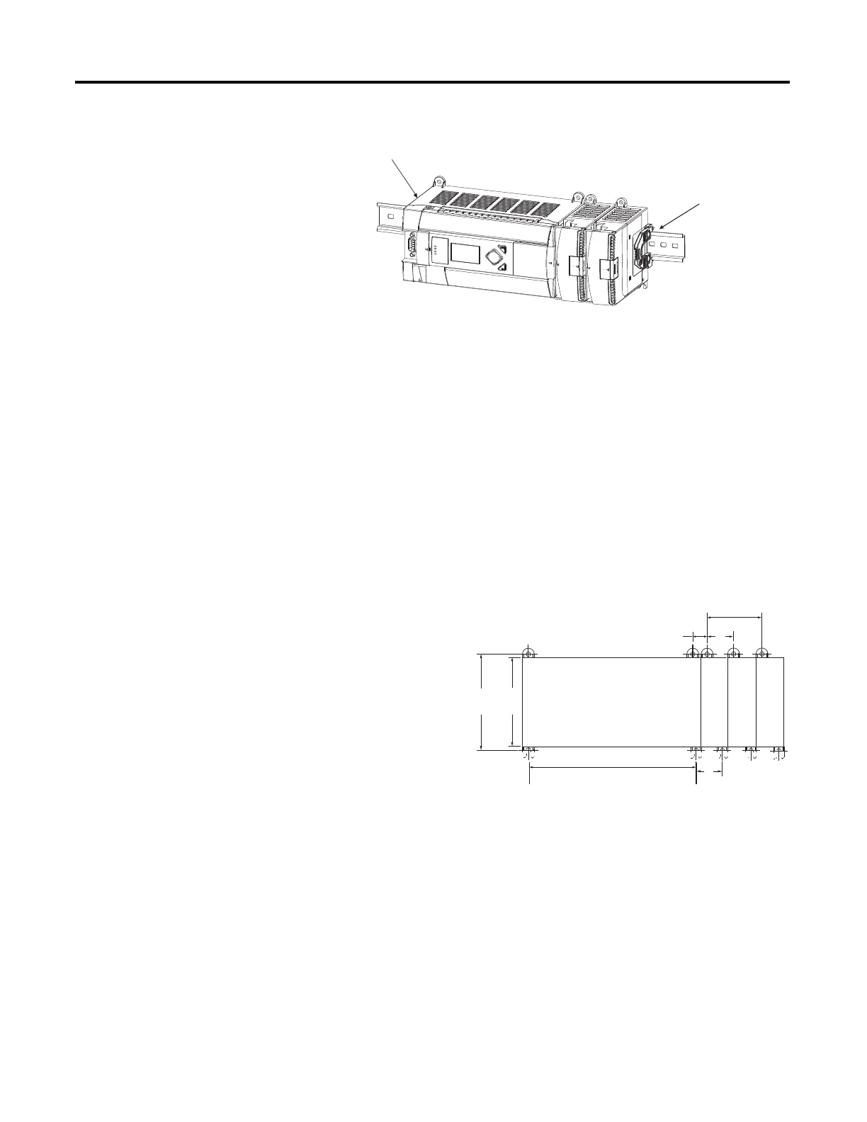
Panel Mounting
Use the dimensional template shown below to mount the module. The preferred
mounting method is to use two M4 or #8 panhead screws per module. Mounting
screws are required on every module.
1762 expansion I/O must be mounted horizontally as illustrated.
For environments with greater vibration and shock concerns, use the
panel mounting method described below, instead of DIN rail
mounting.
End anchor
End anchor
44974
90
(3.54)
100.06
(3.939)
40.4
(1.59)
A
40.4
(1.59)
14.2
(0.568)
MicroLogix
1400
1762 I/O
1762 I/O
1762 I/O
For more than 2 modules: (number of modules - 1) x 40 mm (1.59 in.)
NOTE: All dimensions are in mm
(inches). Hole spacing tolerance:
±0.4 mm (0.016 in.).
A = 165 mm (6.497 in.)
44568

 Loading...


