76 Rockwell Automation Publication 1766-UM001I-EN-P - June 2015
Chapter 4 Communication Connections
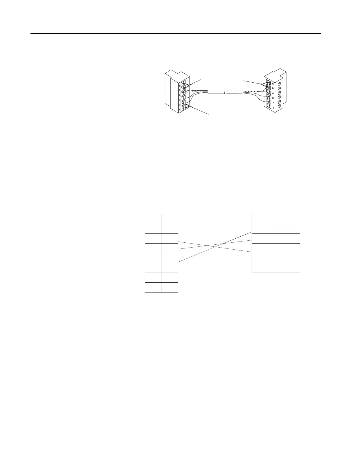
End-of-Line Termination
MicroLogix 1400 Channel 0 to DH-485 Communication Cable Pinout
When connecting MicroLogix 1400 Channel 0 to DH-485 communication
cable pinout using an RS-232 cable, the maximum that the cable length may be
extended is 15.24 m (50 ft). Refer to the following typical pinout:
Connecting the AIC+
You can connect a MicroLogix 1400 controller to a DH-485 network via
Channel 0 directly without using an optical isolator, such as AIC+, catalog
number 1761-NET-AIC, because Channel 0 is isolated. However, you need to
use an AIC+ to connect your PC or other MicroLogix Family products, such as
MicroLogix 1200, to a DH-485 network.
Jumper
Jumper
Belden #3106A or #9842 Cable
1219 m (4000ft) Maximum
Jumper
DTE Device
(MicroLogix
1400
Channel 0)
DCE Device (DH-485
connector)
8-Pin 6-pin
7 TXD 6 Termination
4RXD 5A
2GND 4B
1 B(+) 3 Common
8 A(-) 2 Shield
5 DCD 1 ChassisGround
6CTS
3RTS

 Loading...


