Home
Aritech
Fire Alarms
FP2000 Series
Aritech FP2000 Series Reference Guide
4
of 1
of 1 rating
209 pages
Give review
Manual
Specs
To Next Page
To Next Page
To Previous Page
To Previous Page
Loading...
2. P
ANEL OPER
ATION
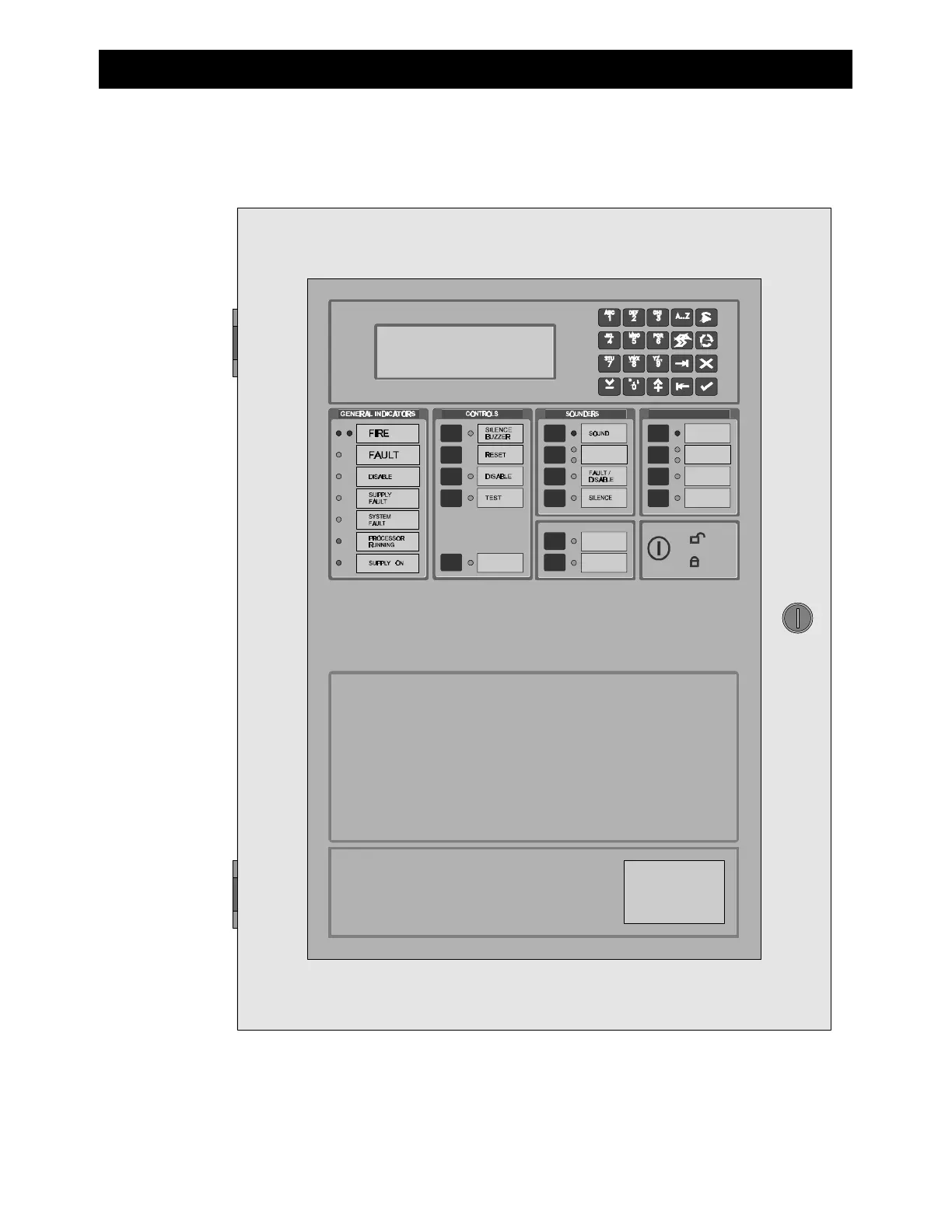
A view of the front of a typical FP2000 Series Fire panel is shown in
Figure
1
below.
Figure
1
: Fire Panel Front View
In order to describe the operation of a FP2000 series fire panel, the front panel has been
divided into two sections, these being:
•
LED indicators and controls
•
LCD and keypad
11
13
Table of Contents
Table of Contents
5
Description
9
Special Features
9
User Friendliness
9
Powerful Maintenance Features
10
Networking
10
General Features
10
Standard I/O Facilities
11
Mechanical Data
11
Led Indications and Controls
13
General Indicators
13
Controls
15
Sounders
15
Fire Brigade
16
Other
17
Zone Indicators
17
LCD and Keypad
18
Start-Up Screens
20
Alarm Line
20
Valid Entries Line
22
Status Line
23
System Status Menu
23
Access to Main Menu
24
Main Menu
25
System Menu
27
Configuration Menu
28
Hardware Configuration 1
29
Version
31
Site Version
32
Hardware Configuration 2
33
Board Information
34
Memory Allocation 1
35
Memory Allocation 2
36
Panel ID
37
Communication Menu
39
Port Setup
40
Network Menu
43
Panels
44
Local Repeaters
45
Global Repeaters
46
Modem Menu
47
Modem Alarm Report 1
48
Modem Alarm Report 2
49
Modem Maintenance
50
Modem Setup 1
51
Modem Setup 2
52
Modem Setup 3
53
CL Devices
54
LON Devices
55
Step-By-Step LON Device Installation Walkthru
57
System Setup
58
System Information
60
System Information 2
60
Access Menu
61
Access Codes
62
Field Access
63
Clear Site Data 1
64
Clear Site Data 2
66
Set Default
67
Set Times Menu
70
Set Date and Time
71
Output Delays
72
Fire Brigade Delay off Times
73
Sounder Delay off Times
74
Zone off Times
75
Zone on Times
76
Day Mode Times
77
Night Mode Times
78
Restart Menu
79
Device Menu
80
General Setup and View (All Types)
81
Smoke and Heat Detectors
85
Manual Call Point
87
Sounder
89
Indicating Circuit Controller
91
Monitor Units
92
Input/Output Units
94
Gas Unit I/O (GCU 1)
96
Zone Menu
98
Area Menu
101
Zone Graphics
103
Zone Graphic Screen
104
Graphic Device Statistics
105
Device Graphics
106
Device Graphic Screen
108
Graphic Device Setup
109
Zone Range
110
Input/Output
111
Common Facilities - All Input Types
113
Input Definition - Type General
116
Input Definition - Type Zone
118
Input Definition - Type Area
119
Input Definition - Type Adjacent Area
120
Input Definition - Type Internal
121
Input Definition - Type Time
122
Input Definition - Type Device Input
124
Input Definition - Type Device
125
Input Definition - Type Network
126
Input Definition - Type Action
127
Input Definition - Type Current Loop Device
128
Input Definition - Type Date
129
Common Facilities - All Output Types
130
Output Definition - Type General
133
Output Definition - Type Zone
134
Output Definition - Type Area
135
Output Definition - Type Internal
136
Output Definition - Type Device Output
137
Output Definition - Type Supervised Internal
138
Output Definition - Type Supervised Device Output
139
Output Definition - Type Network
140
Output Definition - Type Current Loop Device
141
Output Definition - Type Supervised Current Loop
142
Output Definition - Type Event
143
Output Definition - Type Action
144
Output Definition - Link to Equipment
145
Logic
147
CL Devices
150
Timers
152
Markers
153
Event Menu
154
Display Events
155
Clear Event Menu
157
Clear All Events Menu
158
Maintenance Menu
159
Maintenance Report Menu
160
Device Values
161
Device Values [LCD]
162
Maintenance Device
163
Clear Device Statistics
164
Hardware Test
165
Maintenance Times Menu
166
Options Menu
167
Language Menu
168
Operation Menu
169
Device Protocol
170
Loop Test 1
171
Loop Test 2
171
Loop Test 1 - Parameter Screen 1
172
Loop Test 2 - Parameter Screen 2
173
Loop Test 3 - Parameter Screen 1
174
Fast Compensation
175
Main Menu
176
Test Menu
177
Zone Test Menu
178
Zone Test
179
Full Test Report
180
Test Report [LCD]
181
Clear Test Results
182
Exception Test Report
183
Exception Test Report [LCD]
184
Test Devices
185
Output Test
186
Lamp Test
187
Alarm Count
188
User Log
189
Disable Menu
190
Zone Disable
191
Device Disable Menu
192
Alarm Device Disable
193
Manual Device Disable
194
Area Disable
195
Disabled Report Menu
196
Disabled Zones Report
197
Disabled Device Report
198
Disabled Areas Report
199
Output Disable
200
FP2000 Panel Menus
201
Description
201
Other manuals for Aritech FP2000 Series
User Instruction Manual
29 pages
4
Based on 1 rating
Ask a question
Give review
Questions and Answers:
Need help?
Do you have a question about the Aritech FP2000 Series and is the answer not in the manual?
Ask a question
Aritech FP2000 Series Specifications
General
Brand
Aritech
Model
FP2000 Series
Category
Fire Alarms
Language
English
Related product manuals
Aritech FP2000
2 pages
Aritech 2X Series
140 pages
Aritech 1200C
24 pages
Aritech 900 Series
44 pages
Aritech DM2010
4 pages
Aritech 950 Series
44 pages
 Loading...

