Hardware configuration 1
(CONFIGURATION, 1, )
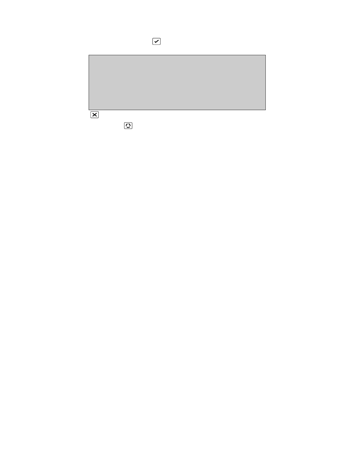
HARDWARE
Ports: 6 Zones : 255 Loops : 2A
Unlocked : 256k Locked RAM : 128k
Relays Sup.Rel. Inputs
Backpanel: 4 4 8
Frontpanel: 0 0 0
more X
Alarms: 0 Faults: 0 Cond.: 0 P: 1 SDZ
Return to Configuration Menu Page 26
Press [More ] to view Version Page 29
This display and the Hardware Configuration 2, 3 and 4 displays show the hardware
configuration of the fire panel. The particular configuration will be determined by the
model number of the FP2000 as well as any optional boards that may have been
installed.
The screen will show:
Ports -
The number of ports installed.
The standard ports are:
FEP Port (not accessible to the user)
Current Loop (for fireman’s panels)
Ser1 RS232 Serial port 1
Ser2 RS232 Serial port 2
ARC 1 Arcnet port 1
LON port
Zones -
The number of displayable zones equipped.
Loops -
The number of loops equipped and whether the loop driver boards are connected in
Class A or Class B configuration. Each loop board accommodates two Class A loops or
four Class B loops.
Unlocked RAM -
The amount of RAM installed that is not controlled by the memory lock switch.
Locked RAM -
The amount of RAM installed that is controlled by the memory lock switch. Locked RAM
is used for site data.
*See Memory Allocation, Page 33 for more information relating to memory size.
 Loading...

