Main menu
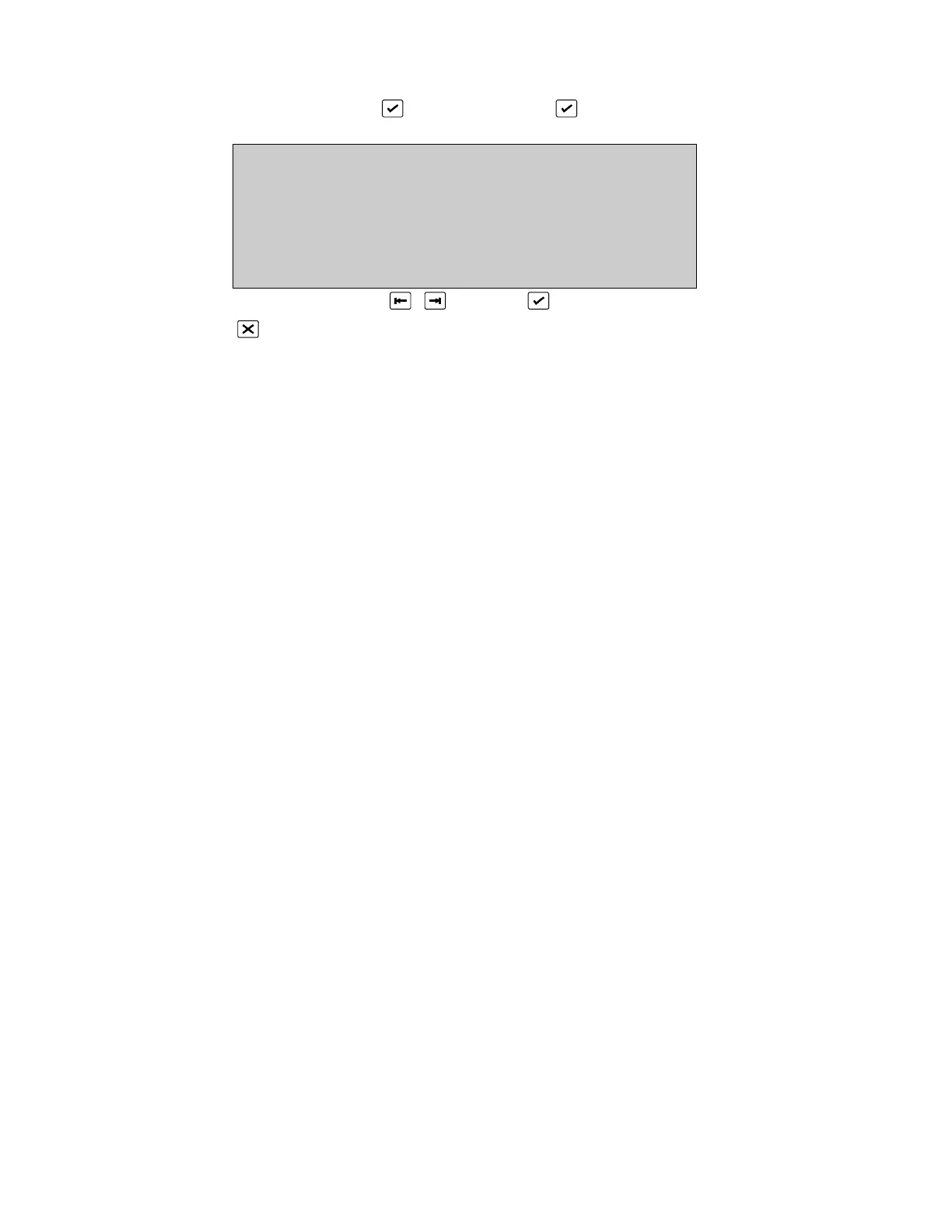
(SYSTEM STATUS, , CORRECT CODE, )
MAIN MENU
1 System 2 Devices
3 Input/Output 4 Events
5 Maintenance 6 Test/Disable
0. .9, <>, E, X
Alarms: 0 Faults: 0 Cond.: 0 P: 1 SDZ
Select number or use and press
Return to System Status *See Chapter 3.
1 System Menus Page 25
2 Device Menus Page 78
3 Input, Output and Logic Page 109
4 Event Log Page 152
5 Maintenance Menus Page 157
6 Test and Disable Functions Page 175 (Test menu)
Page 188 (Disable Menu)
All data of the fire panel may be viewed and/or changed by persons authorised to do so.
In order to view any screen requires the correct access code(s). In order to change data,
the user requires both the correct access code and the memory must be unlocked. The
memory lock switch is located on the Host CPU board and thus access is required within
the cabinet in order to change data.
The Main Menu provides a logical subdivision of the fire panel data and facilities.
• System - The viewing/programming of the fire panel internal system. Items such as
the serial ports, RAM memory, operation, date/time and timings are accessed.
• Devices - The viewing/programming of all facilities of the devices connected to the
loops of the fire panel. This includes the zoning and statistics of each device as well
as graphic screens.
• Input/Output - The definition of inputs and outputs, as well as the logic defining the
operation of the fire panel according to input/output. Inputs and outputs are derived
from the internal system, I/O devices on the loop, and network.
• Events - The examination and selective printing of the event log. The event log is also
cleared in this menu.
• Maintenance - The facilities provided in order to completely maintain the fire panel
system and the devices on the loop. This includes a host of reporting facilities.
 Loading...

