Output definition – type Internal
(INPUT/OUTPUT, 2, )
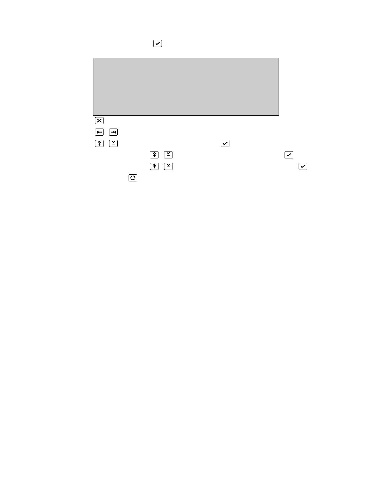
OUTPUT DEFINITION State :false
Output :1 Trig. :latched
Type :Internal Mode :normal
Board :17:VDS continuous
Output :1 unlogged
More 0. .9, ^V, <>, E, X
Alarms: 0 Faults: 0 Cond.: 0 P: 1 SDZ
Return to Input/Output Menu Page 109
Place cursor at TYPE
Select Type: INTERNAL and press (Unlock memory!)
Use number 0..9 or to select PC Board address and press
Use number 0..9 or to select PC Board input number and press
Press [More ] to view Screen 2 of the outputs.
*See Common Facilities - All Output Types, Page 128 for a description of Output, State,
Trigger, Mode, Event and Text
The output number selects the relay provided on a printed circuit board within the FP2000
fire panel. In order to assign a physical relay, the PC Board address (see Page 32 for
board addressing) as well as the relay number on that board must be defined.
The FP2000 provides four programmable relays on the Sounder board (address 17) as
standard. *See Hardware Configuration (Page 27) for installed PCB addresses.
This screen confirms the PC Board type when the board address is entered.
Trigger: Latched/unlatched
Mode: Normal/inverted
Continuous/pulse/pulsing
Unlogged/Logged
Text: Allowed
* See Output Description in the Serial Communication Format
 Loading...

