Output definition – type Network
(INPUT/OUTPUT, 2, )
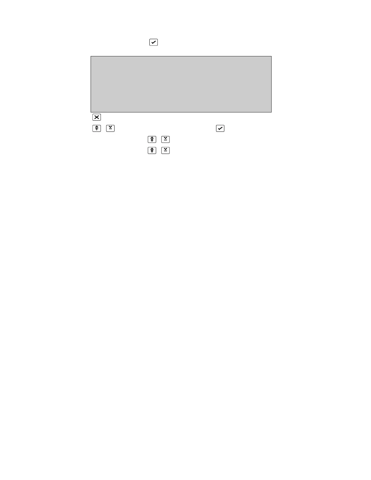
OUTPUT DEFINITION State :false
Output :1 Trig. :latched
Type :Network Mode :normal
Node :01/01 continuous
Input :1 unlogged
0. .9, ^V, <>, E, X
Alarms: 0 Faults: 0 Cond.: 0 P: 1 SDZ
Return to Input/Output Menu Page 109
Select Type: NETWORK and press
Use number or 0...9 to select Panel address that the output is sent to
Use number or 0...9 to select the Input on that panel that the output must
activate
The output will switch the input of another node (panel) connected on the network.
Node: The node ID of whereto the output is sent
Input: The input number setup in the input definition of the selected
(receiving) node.
Trigger: Latched/unlatched
Mode: Normal/inverted
Continuous only
Unlogged/logged
Text: Allowed
Please refer to the Network Configuration Guide (LKFP2303) for the exact way of
operation.
* See Output Description in the Serial Communication Format
 Loading...

