Parts lists, drawings and replacement
2001989-203C ApexPro™ Telemetry 7-25
022A
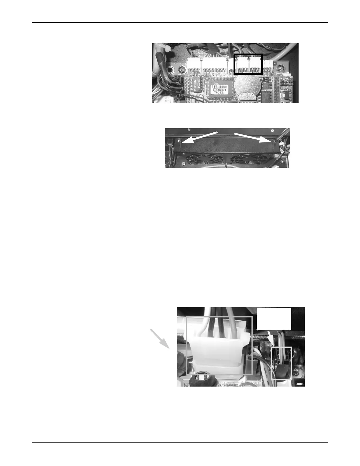
4. Using a phillips screwdriver, remove the 2 screws securing the cabinet fan
assembly at the front of the chassis. Remove the fan assembly.
101A
5. Remove the fan from the fan assembly.
6. Reverse the steps in this procedure to install the CPU fan.
CPU boards
1. Complete the preparation procedures. See Field replacement preparation on page
7-3.
2. Disconnect all jacks and plugs from the CPU board I/O ports at the back of the
ATS .
3. Remove the chassis cover. See Chassis cover on page 7-6.
4. Disconnect the CD data cable connector from the main CPU board.
5. Disconnect the power, and temperature sensor connectors from the receptacles
near the front left corner of the main CPU board. Note the position and
orientation of the connectors for reassembly.
097A
6. Disconnect the ATX, serial port and USB connectors from the receptacles near
the back left corner of the main CPU board. Note the position and orientation of
the connectors for reassembly.
Power
connector
Temperature
sensor
connector
 Loading...


