3-14 ApexPro™ Telemetry 2001989-203C
Installation
Unity Network RX network connection
Connect the ATS Unity Network RX network ethernet port to the ApexPro receiver
subsystem ethernet port as indicated above.
The ATS requires a dedicated connection to the ApexPro receiver subsystem.
If the distance between the ATS and the ApexPro Receiver Subsystem is less
than 100 meters (328 ft.), connect the devices point-to-point with a crossover
cable (null modem) connection.
If the distance is greater than 100 meters (328 ft.), use either an additional hub or
use a fiber optic cable.
Power up
NOTE
ATS power supplies automatically adjust to input power sources within the
specified limits. See Technical specifications on page A-2.
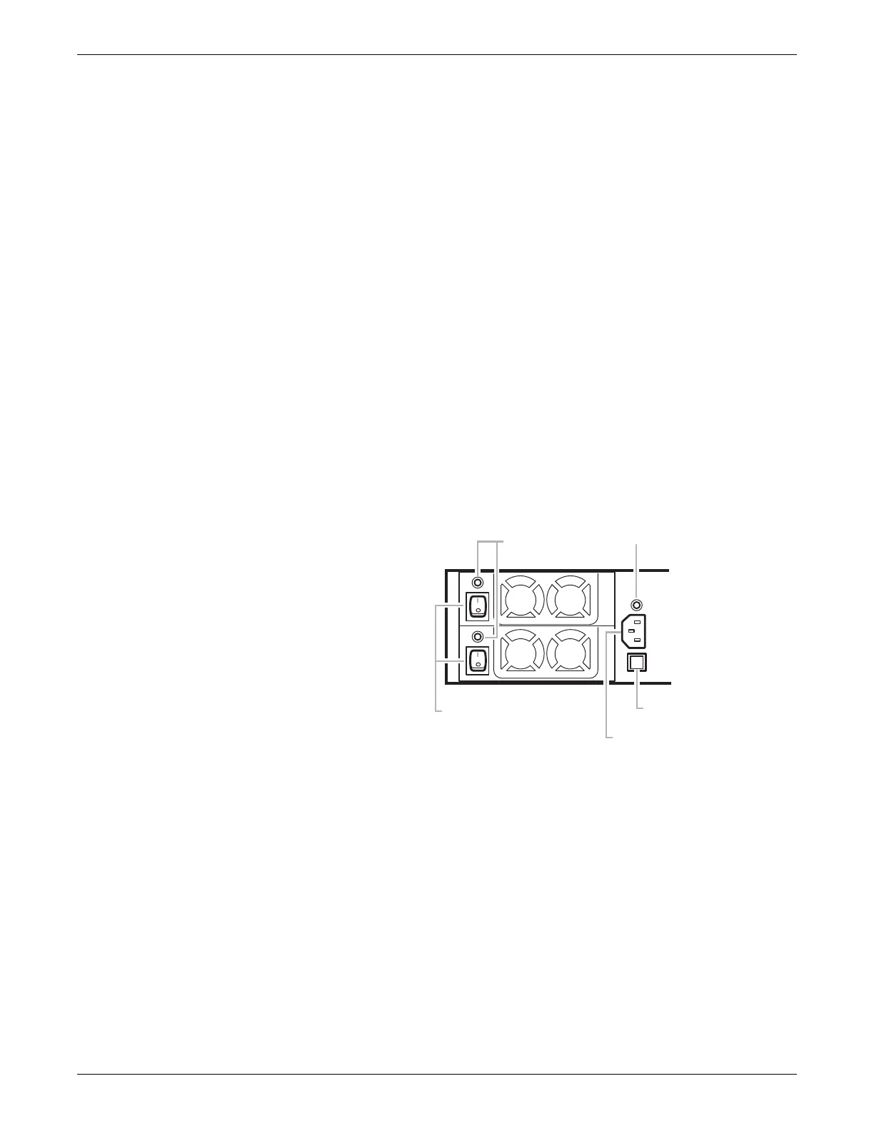
1. Plug the power cord into the power cord receptacle in back of the ATS.
136A
2. Plug the 3-pronged ATS power cord into an approved activated UPS device.
3. Switch both ATS power supply switches on. The power supply status LEDs are
green when the power supplies are properly activated.
4. Press and momentarily hold the power switch on the front of the ATS. The ATS
starts up in normal user mode.
NOTE
To interrupt the normal startup procedure and log into the ATS as a different
user requires connecting a keyboard/mouse and a monitor. Hold down the
Shift key during startup.
BACK PANEL
Power supply
status LEDs
Power cord
connector
Power supply
switches
Power supply
status LED
Alarm Reset
button
 Loading...


