7-30 ApexPro™ Telemetry 2001989-203C
Parts lists, drawings and replacement
040A
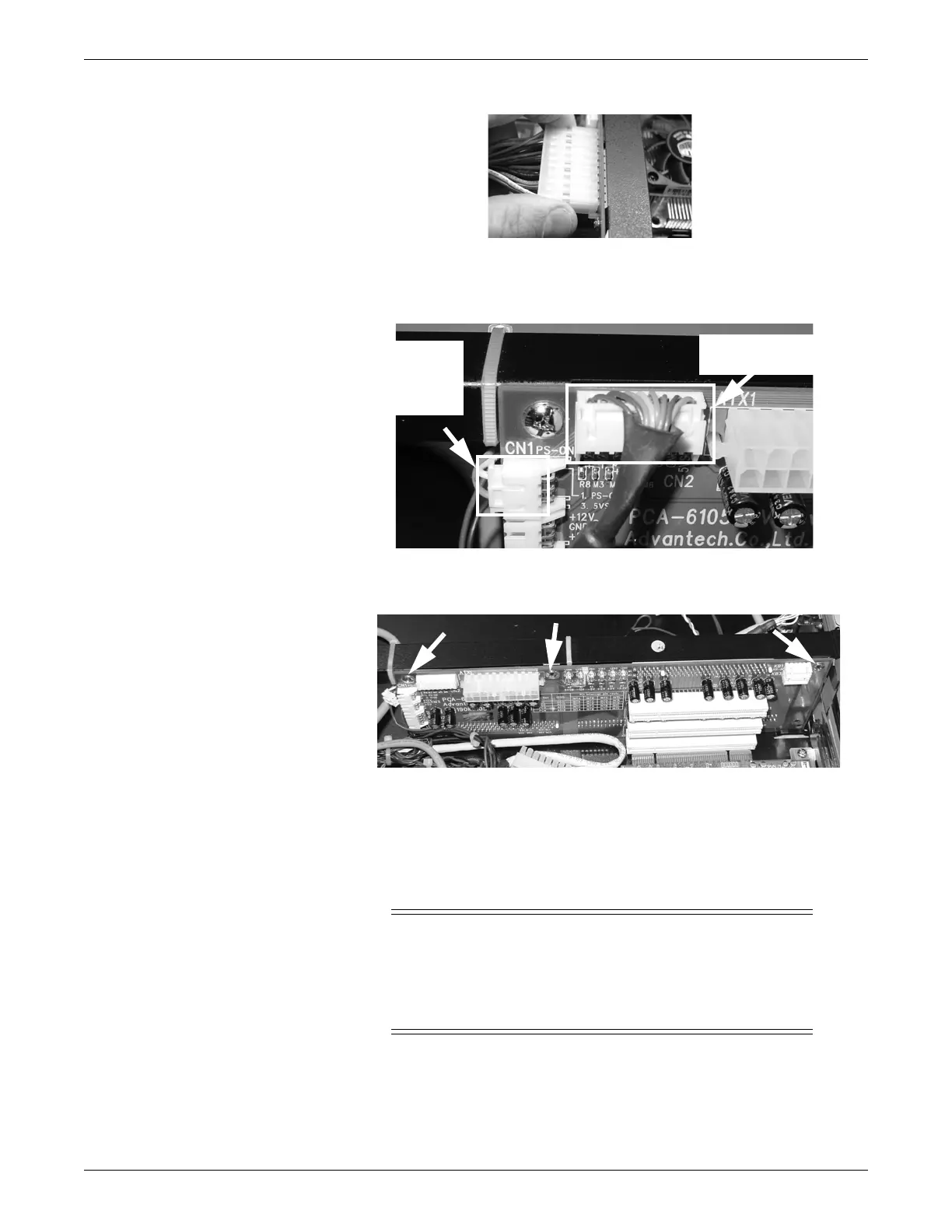
23. Disconnect the ATX feature select and backplane voltage monitor connectors
from the top front corner of the CPU riser board. Note the position and
orientation of the connectors for reassembly
213A
24. Using a phillips screwdriver, remove (for installation) the three screws securing
the CPU riser board to the chassis.
212A
25. Lift the CPU riser board up and out of the chassis.
26. Reverse the steps in this procedure to install the CPU boards.
Power module
WARNING
SHOCK HAZARD — Never open the power supply.
There are no field serviceable components inside. Capacitors inside
the power supply case present a shock hazard even with the power
switched off and the power cord removed.
ATX feature
select
connector
Backplane voltage
monitor connector
 Loading...


