D
IRECTION FR091521, REVISION 1 VIVID S60N/VIVID S70N BASIC SERVICE MANUAL
8-128 Section 8-5 - Electronic Cage Components - Replacement Procedures
PRELIMINARY
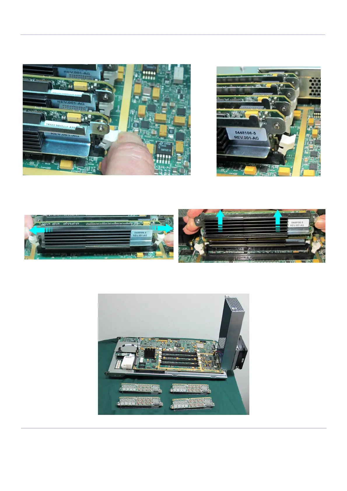
Note: The four TRX32 Boards are each secured in position on the CFE Board by way of a white
plastic holder at each end of the TRX32 Board. These are opened by gently pulling them
outwards to tilt the holder away from the edge of the Board, as shown in Figure 8-154.
4.) Open each white plastic holder located on either end of the first TRX32 Board to release the board,
then slide the Board upwards to remove it.
5.) Repeat step 4 to remove each of the remaining TRX32 Boards - Figure 8-156.
Figure 8-154 TRX32 Boards Secured with Plastic Holders
Figure 8-155 Removing a TRX32 Board
Figure 8-156 All TRX32 Boards Removed

 Loading...


