5
Figure 3 shows how an MCE maintains the routing entries of multiple VPNs and how an MCE exchanges
VPN routes with PEs.
Figure 3 Network diagram for the MCE function
On the left-side network, there are two VPN sites, both of which are connected to the MPLS backbone
through the MCE device. VPN 1 and VPN 2 on the left-side network must establish a tunnel with VPN 1
and VPN 2 on the right-side network, respectively.
With the MCE function, you can create a routing table for VPN 1 and VPN 2 on the MCE device, and
bind VLAN-interface 2 with VPN 1 and VLAN-interface 3 with VPN 2. When receiving a routing
message, the MCE device can determine the source of the routing information according to the inbound
interface, and then update the routing table of the corresponding VPN.
In addition, you must perform configurations on PE 1 to bind the interfaces connecting the MCE with the
VPNs in the same way as you do on the MCE device. The MCE device and PE 1 must be connected
through a trunk link to allow packets of VLAN 2 and VLAN 3. When receiving a packet, PE 1 can
determine which VPN the packet belongs to and then passes the packet to the right tunnel.
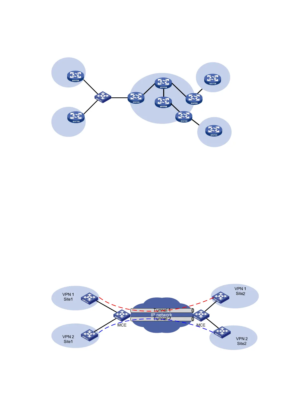
Using MCE in tunneling applications
In addition to MPLS L3VPN, you can also use tunneling technologies to implement other types of VPNs.
The MCE function provided by the switch can be applied in VPN applications based on tunneling.
Figure 4 Network diagram for using MCE in a tunneling application (1)
PE1
PE
PE2
P
P
VPN 2
Site 2
VPN 1
Site 1
MCE
VLAN-int2
VLAN-int3
CE
Site 1
VPN 2
CE
VPN 1
Site 2
VLAN-int7
VLAN-int8