132
# Create a static route to direct traffic to the MPLS TE tunnel.
[SwitchA] ip route-static 3.2.1.2 24 tunnel 0 preference 1
# Execute the display ip routing-table command on Switch A. You can see a static route entry with
interface Tunnel 0 as the outgoing interface.
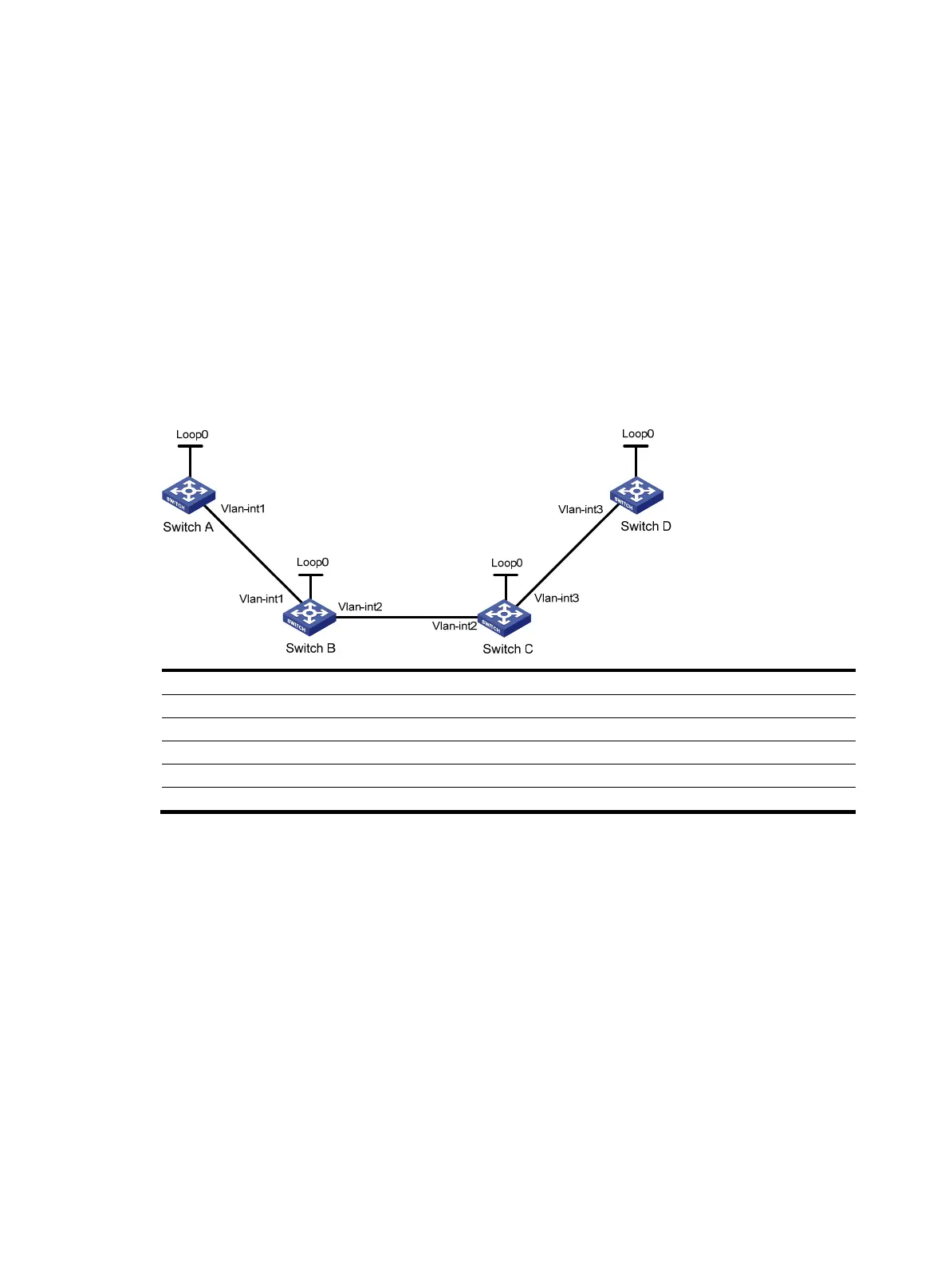
MPLS TE using RSVP-TE configuration example
Network requirements
Switch A, Switch B, Switch C, and Switch D are running IS-IS and all of them are Level-2 devices.
Use RSVP-TE to create a TE tunnel with 2000 kbps of bandwidth from Switch A to Switch D, making sure
the maximum bandwidth of each link that the tunnel traverses is 10000 kbps and the maximum
reservable bandwidth is 5000 kbps.
Figure 32 Network diagram
Device Interface IP address
Device
Interface
IP address
Switch A Loop0 1.1.1.9/32 Switch D Loop0 4.4.4.9/32
Vlan-int1 10.1.1.1/24
Vlan-int3
30.1.1.2/24
Switch B Loop0 2.2.2.9/32
Switch C
Loop0
3.3.3.9/32
Vlan-int1 10.1.1.2/24 Vlan-int3 30.1.1.1/24
Vlan-int2 20.1.1.1/24
Vlan-int2
20.1.1.2/24
Configuration procedure
1. Configure IP addresses and masks for interfaces according to Figure 32. (Details not shown.)
2. Enable IS-IS to advertise host routes with LSR IDs as destinations:
# Configure Switch A.
<SwitchA> system-view
[SwitchA] isis 1
[SwitchA-isis-1] network-entity 00.0005.0000.0000.0001.00
[SwitchA-isis-1] quit
[SwitchA] interface vlan-interface 1
[SwitchA-Vlan-interface1] isis enable 1
[SwitchA-Vlan-interface1] isis circuit-level level-2
[SwitchA-Vlan-interface1] quit
[SwitchA] interface loopback 0
[SwitchA-LoopBack0] isis enable 1
[SwitchA-LoopBack0] isis circuit-level level-2