361
Configuring IPv6 MPLS L3VPNs
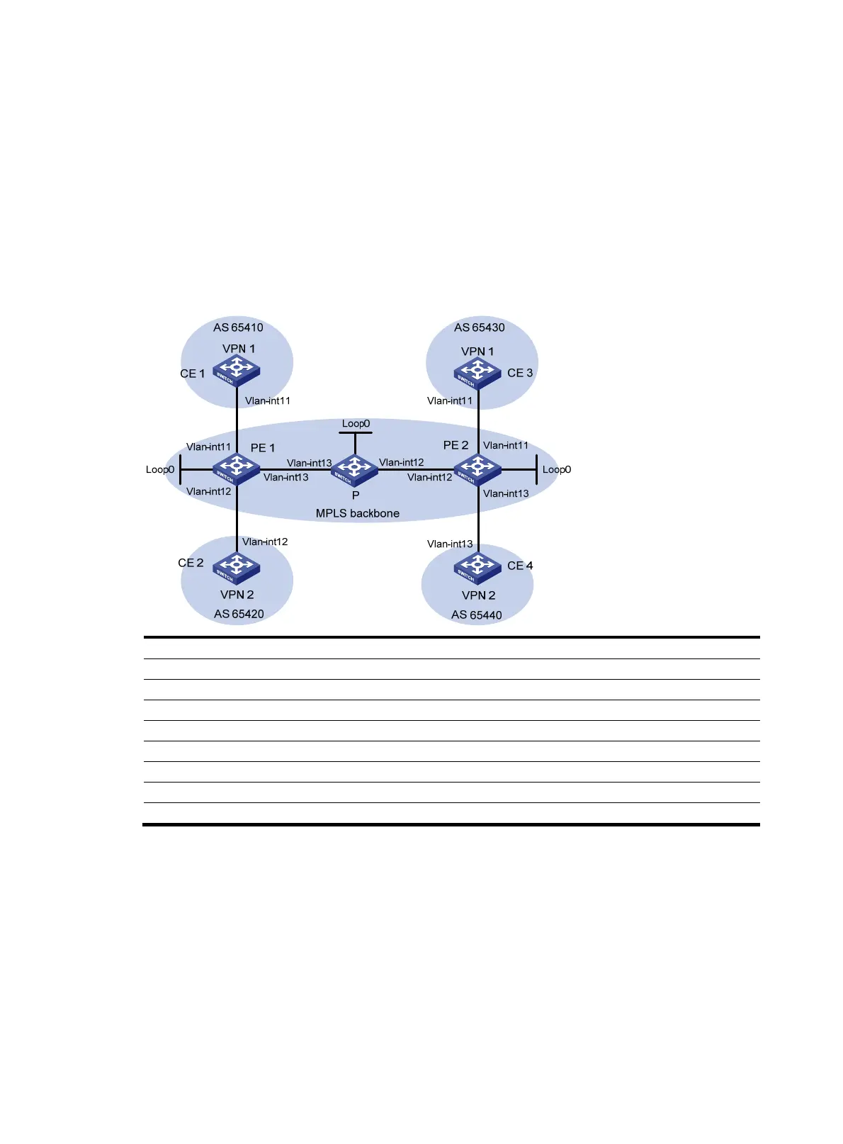
Network requirements
CE 1 and CE 3 belong to VPN 1. CE 2 and CE 4 belong to VPN 2.
VPN 1 uses route target attributes 111:1. VPN 2 uses route target attributes 222:2. Users of different VPNs
cannot access each other.
EBGP is used to exchange VPN routing information between CE and PE switches.
PEs use OSPF to communicate with each other and use MP-IBGP to exchange VPN routing information.
Figure 45 Network diagram
Device Interface IP address Device Interface IP address
CE 1 Vlan-int11 2001:1::1/96
P
Loop0
2.2.2.9/32
PE 1 Loop0
1.1.1.9/32
Vlan-int12 172.2.1.1/24
Vlan-int11 2001:1::2/96 Vlan-int13 172.1.1.2/24
Vlan-int13 172.1.1.1/24
PE 2
Loop0
3.3.3.9/32
Vlan-int12 2001:2::2/96
Vlan-int12 172.2.1.2/24
CE 2 Vlan-int12 2001:2::1/96 Vlan-int11 2001:3::2/96
CE 3 Vlan-int11 2001:3::1/96
Vlan-int13 2001:4::2/96
CE 4 Vlan-int13 2001:4::1/96
Configuration procedure
1. Configure OSPF on the MPLS backbone to achieve IP connectivity among the PEs and the P switch:
# Configure PE 1.
<PE1> system-view
[PE1] interface loopback 0
[PE1-LoopBack0] ip address 1.1.1.9 32
[PE1-LoopBack0] quit
[PE1] interface vlan-interface 13
[PE1-Vlan-interface13] ip address 172.1.1.1 24
[PE1- Vlan-interface13] quit
 Loading...


