343
--- 200.1.1.1 ping statistics ---
5 packet(s) transmitted
5 packet(s) received
0.00% packet loss
round-trip min/avg/max = 66/79/109 ms
Configuring BGP AS number substitution and SoO
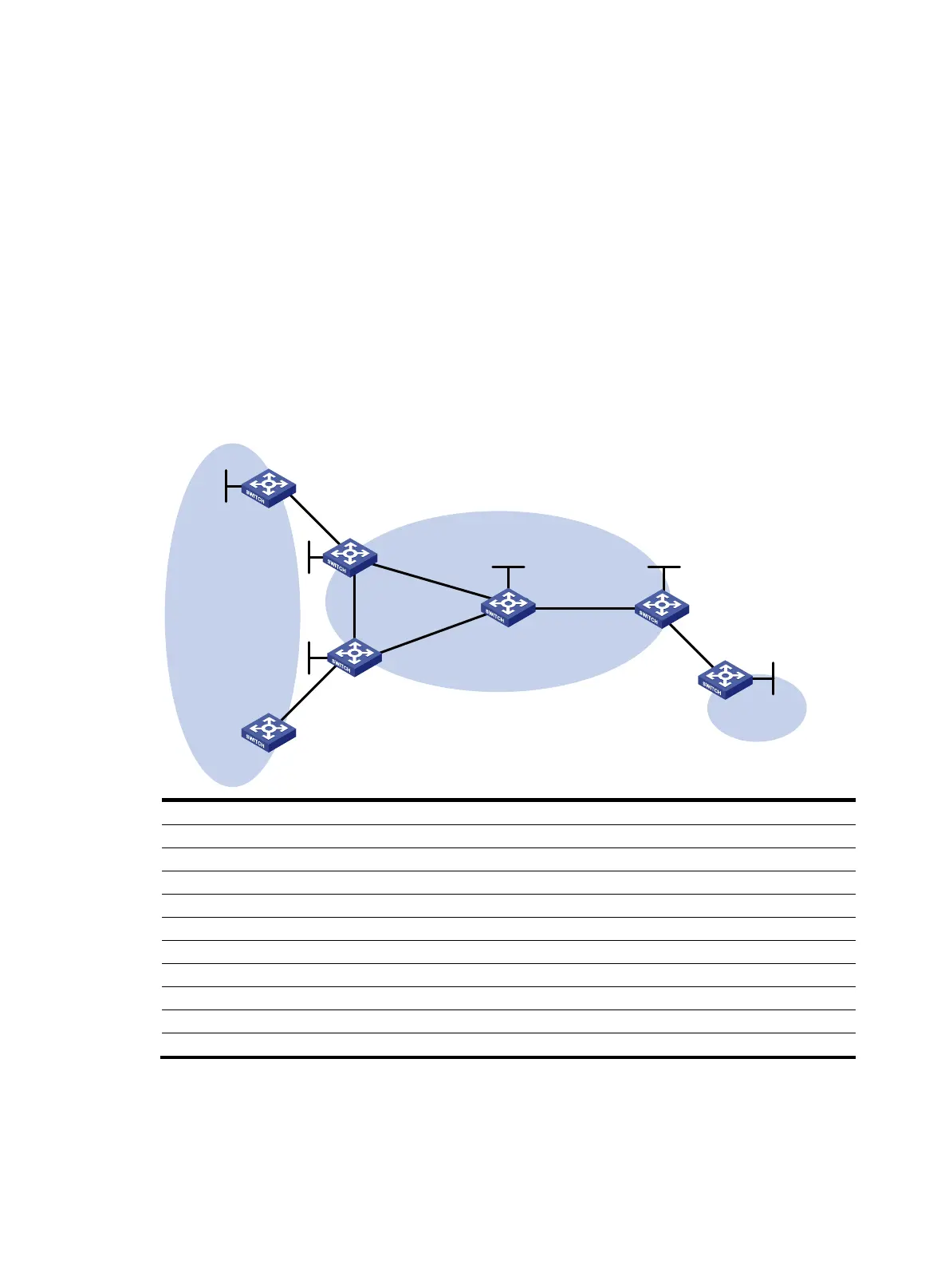
Network requirements
CE 1, CE 2, and CE 3 belong to VPN 1 and connect to PE1, PE 2, and PE 3, respectively. CE 1 and CE
2 reside in the same site. CE1, CE2, and CE 3 all use AS number 600.
To avoid route loss, configure BGP AS number substitution on PEs. To avoid routing loops, configure a
routing policy on PE1 and PE2 to add the SoO attribute to routes received from CE 1 and CE 2.
Figure 42 Network diagram
Device Interface IP address
Device
Interface
IP address
CE 1 Loop0 100.1.1.1/32
CE 3
Loop0
200.1.1.1/32
Vlan-int2 10.1.1.1/24 Vlan-int7 10.3.1.1/24
CE 2 Vlan-int2 10.2.1.1/24
PE 2
Loop0
2.2.2.9/32
PE 1 Loop0 1.1.1.9/32
Vlan-int2
10.2.1.2/24
Vlan-int2 10.1.1.2/24 Vlan-int4 20.1.1.2/24
Vlan-int3 30.1.1.1/24
Vlan-int5
40.1.1.1/24
Vlan-int4 20.1.1.1/24
P
Loop0
3.3.3.9/32
PE 3 Loop0 4.4.4.9/32 Vlan-int3 30.1.1.2/24
Vlan-int6 50.1.1.2/24
Vlan-int5
40.1.1.2/24
Vlan-int7 10.3.1.2/24
Vlan-int6
50.1.1.1/24
Configuration procedure
1. Configure basic MPLS L3VPN:
{ Configure OSPF on the MPLS backbone to allow the PEs and P device to learn the routes of the
loopback interfaces from each other.
Loop0
Loop0
Loop0
PE 1
P
PE 3
CE 2
CE 3
VPN 1
AS 600
VPN 1
AS 600
Vlan-int6
Vlan-int6
Vlan-int7
Vlan-int2
Vlan-int2
MPLS backbone
AS 100
CE 1
Vlan-int2
Vlan-int2
Loop0
Vlan-int4
Vlan-int3
PE 2
Vlan-int4
Vlan-int5
Vlan-int3
Vlan-int5
Vlan-int7
Loop0
Loop0
 Loading...