82
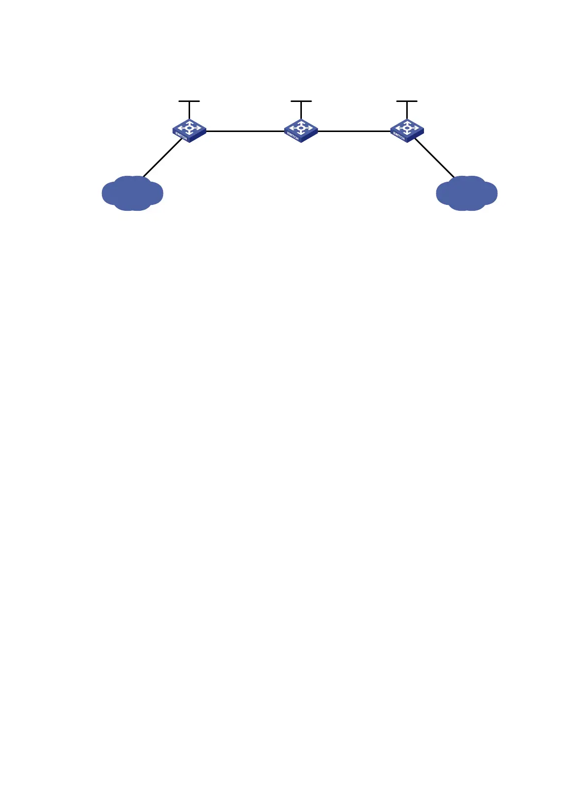
Figure 24 Network diagram
Configuration considerations
• On an LSP, the out label of an upstream LSR must be identical with the in label of its downstream
LSR.
• Configure an LSP for each direction on the forwarding path.
• Configure a static route to the destination address of the LSP on each ingress node. Such a route is
not required on the transit and egress nodes. You do not need to configure any routing protocol on
the switches.
Configuration procedure
1. Configure IP addresses for interfaces. (Details not shown.)
2. Configure a static route to the FEC destination address on each ingress node:
# Configure a static route to network 21.1.1.0/24 on Switch A.
<SwitchA> system-view
[SwitchA] ip route-static 21.1.1.0 24 10.1.1.2
# Configure a static route to network 11.1.1.0/24 on Switch C.
<SwitchC> system-view
[SwitchC] ip route-static 11.1.1.0 255.255.255.0 20.1.1.1
3. Enable MPLS:
# Configure MPLS on Switch A.
[SwitchA] mpls lsr-id 1.1.1.9
[SwitchA] mpls
[SwitchA-mpls] quit
[SwitchA] interface vlan-interface 2
[SwitchA-Vlan-interface2] mpls
[SwitchA-Vlan-interface2] quit
# Configure MPLS on Switch B.
[SwitchB] mpls lsr-id 2.2.2.9
[SwitchB] mpls
[SwitchB-mpls] quit
[SwitchB] interface vlan-interface 2
[SwitchB-Vlan-interface2] mpls
[SwitchB-Vlan-interface2] quit
[SwitchB] interface vlan-interface 3
[SwitchB-Vlan-interface3] mpls
Loop0
2.2.2.9/32
Vlan-int3
20.1.1.1/24
Loop0
3.3.3.9/32
Loop0
1.1.1.9/32
Vlan-int2
10.1.1.1/24
Vlan-int2
10.1.1.2/24
Vlan-int3
20.1.1.2/24
Switch A Switch B Switch C
11.1.1.0/24 21.1.1.0/24
Vlan-int4
11.1.1.1/24
Vlan-int5
21.1.1.1/24
 Loading...


