84
0.00% packet loss
round-trip min/avg/max = 1/1/2 ms
# On Switch C, test the connectivity of the LSP from Switch C to Switch A.
[SwitchC] ping lsp -a 21.1.1.1 ipv4 11.1.1.0 24
LSP Ping FEC: IPV4 PREFIX 11.1.1.0/24 : 100 data bytes, press CTRL_C to break
Reply from 10.1.1.1: bytes=100 Sequence=1 time = 3 ms
Reply from 10.1.1.1: bytes=100 Sequence=2 time = 2 ms
Reply from 10.1.1.1: bytes=100 Sequence=3 time = 2 ms
Reply from 10.1.1.1: bytes=100 Sequence=4 time = 2 ms
Reply from 10.1.1.1: bytes=100 Sequence=5 time = 2 ms
--- FEC: IPV4 PREFIX 11.1.1.0/24 ping statistics ---
5 packet(s) transmitted
5 packet(s) received
0.00% packet loss
round-trip min/avg/max = 2/2/3 ms
Configuring LDP to establish LSPs dynamically
Network requirements
Switch A, Switch B, and Switch C support MPLS.
Configure LDP to establish LSPs between Switch A and Switch C so that subnets 11.1.1. 0 / 24 a n d
21.1.1.0/24 can reach each other over MPLS. Test the connectivity of the LSPs.
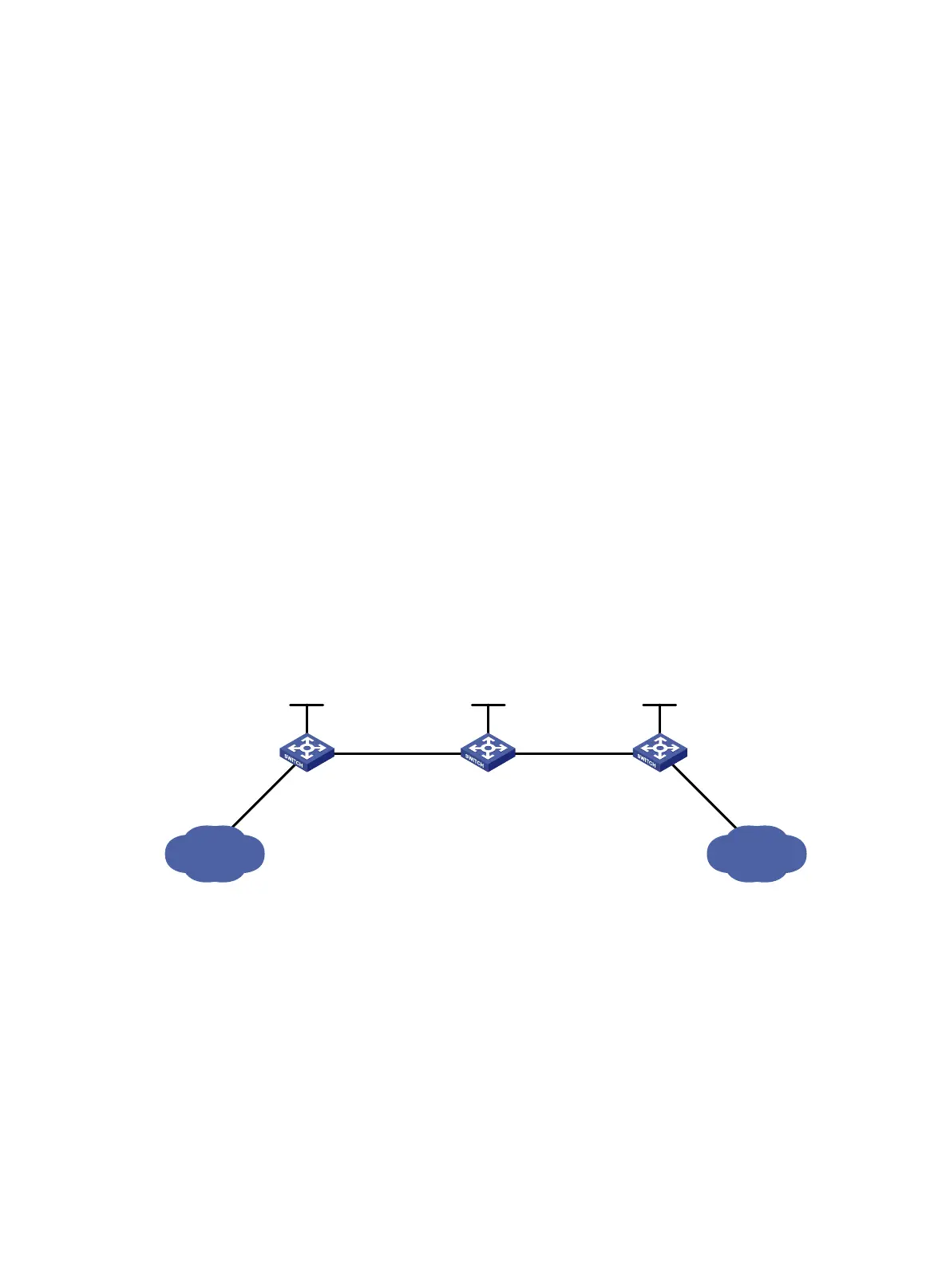
Figure 25 Network diagram
Configuration considerations
• Enable LDP on the LSRs. LDP dynamically distributes labels and establishes LSPs and thus there is no
need to manually configure labels for LSPs.
• LDP uses routing information for label distribution. You must configure a routing protocol to learn
routing information. OSPF is used in this example.
Configuration procedure
1. Configure IP addresses for interfaces. (Details not shown.)
2. Configure OSPF to ensure IP connectivity between the switches:
# Configure OSPF on Switch A.
<Sysname> system-view
Loop0
2.2.2.9/32
Vlan-int3
20.1.1.1/24
Loop0
3.3.3.9/32
Loop0
1.1.1.9/32
Vlan-int2
10.1.1.1/24
Vlan-int2
10.1.1.2/24
Vlan-int3
20.1.1.2/24
Switch A Switch B Switch C
11.1.1.0/24 21.1.1.0/24
Vlan-int4
11.1.1.1/24
Vlan-int5
21.1.1.1/24