175
Binding service instances with VPLS instances
Network requirements
CE 1 and CE 2 are connected to PE 1 and PE 2 through VLANs.
On PE 1 and PE 2, perform the following configuration:
• Configure VPLS instance aaa to use LDP (Martini mode) and VPLS instance bbb to use BGP
(Kompella mode), and configure the AS number as 100.
• Configure service instance 1000 to match packets that are received on GigabitEthernet 1/0/1 and
carry the VLAN tag of 100. Bind service instance 1000 to VPLS instance aaa.
• Configure service instance 2000 to match packets that are received on GigabitEthernet 1/0/1 and
carry VLAN tag of 200. Bind service instance 2000 to VPLS instance bbb.
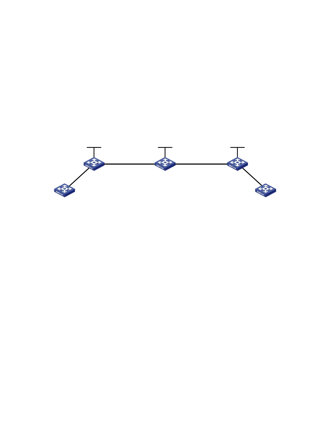
Figure 43 Network diagram
Configuration procedure
1. Configure PE 1:
# Configure an IP address for loopback 0.
<Sysname> system-view
[Sysname] sysname PE1
[PE1] interface loopback 0
[PE1-LoopBack0] ip address 1.1.1.9 32
[PE1-LoopBack0] quit
# Configure the LSR ID and enable MPLS globally.
[PE1] mpls lsr-id 1.1.1.9
[PE1] mpls
[PE1-mpls] quit
# Enable L2VPN and MPLS L2VPN.
[PE1] l2vpn
[PE1-l2vpn] mpls l2vpn
[PE1-l2vpn] quit
# Enable LDP globally.
[PE1] mpls ldp
[PE1-mpls-ldp] quit
# Configure PE 1 to establish an LDP remote session with PE 2.
[PE1] mpls ldp remote-peer 1
[PE1-mpls-ldp-remote-1] remote-ip 3.3.3.9
Loop 0
1.1.1.9/24
Loop 0
2.2.2.9/24
Loop
3.3.3.9/24
PE 1
GE1/0/
1
P PE 2
CE 2CE 1
GE1/0/1
Vlan -int3
26.2.2.1/24
Vlan-int2
23.1.1 .1/24
Vlan -int2
23 .1.1.2/ 24
Vlan-int3
26.2.2.2/24