328
--- 130.1.1.1 ping statistics ---
5 packet(s) transmitted
0 packet(s) received
100.00% packet loss
Configuring HoVPN
Network requirements
There are two levels of networks, the backbone and the MPLS VPN networks, as shown in Figure 39.
• SPEs act as PEs to allow MPLS VPNs to access the backbone.
• UPEs act as PEs of the MPLS VPNs to allow end users to access the VPNs.
• Performance requirements for the UPEs are lower than those for the SPEs.
• SPEs advertise routes permitted by the routing policies to UPEs, permitting CE 1 and CE 3 in VPN
1 to communicate with each other and forbidding CE 2 and CE 4 in VPN 2 to communicate with
each other.
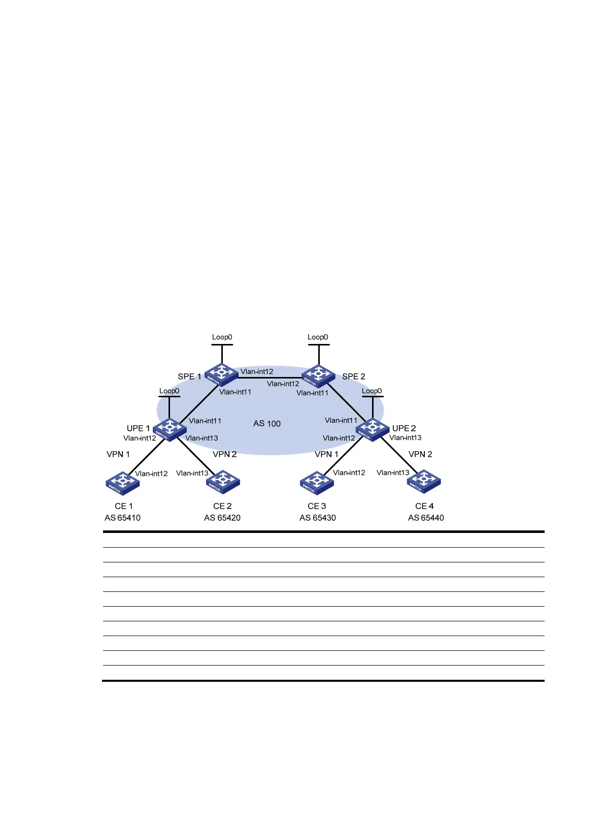
Figure 39 Network diagram
Device Interface IP address
Device
Interface
IP address
CE 1 Vlan-int12 10.2.1.1/24 CE 3 Vlan-int12 10.1.1.1/24
CE 2 Vlan-int13 10.4.1.1/24
CE 4
Vlan-int13 10.3.1.1/24
UPE 1 Loop0 1.1.1.9/32
UPE 2
Loop0
4.4.4.9/32
Vlan-int11 172.1.1.1/24 Vlan-int11 172.2.1.1/24
Vlan-int12 10.2.1.2/24
Vlan-int12 10.1.1.2/24
Vlan-int13 10.4.1.2/24
Vlan-int13 10.3.1.2/24
SPE 1 Loop0 2.2.2.9/32 SPE 2 Loop0 3.3.3.9/32
Vlan-int11 172.1.1.2/24
Vlan-int11 172.2.1.2/24
Vlan-int12 180.1.1.1/24
Vlan-int12 180.1.1.2/24
Configuration procedure
1. Configure UPE 1:
# Configure basic MPLS and MPLS LDP to establish LDP LSPs.
 Loading...