140
[SwitchA] mpls
[SwitchA-mpls] mpls rsvp-te graceful-restart
# Configure Switch B.
<SwitchB> system-view
[SwitchB] mpls
[SwitchB-mpls] mpls rsvp-te graceful-restart
# Configure Switch C.
<SwitchC> system-view
[SwitchC] mpls
[SwitchC-mpls] mpls rsvp-te graceful-restart
7. Verify the configuration:
After the configuration, a tunnel is created between Switch A and Switch C. Execute the display
mpls rsvp-te peer command.
<SwitchA> display mpls rsvp-te peer
Interface Vlan-interface1
Neighbor Addr: 10.1.1.2
SrcInstance: 880 NbrSrcInstance: 5017
PSB Count: 0 RSB Count: 1
Hello Type Sent: REQ Neighbor Hello Extension: ENABLE
SRefresh Enable: NO
Graceful Restart State: Ready
Restart Time: 120 Sec Recovery Time: 300 Sec
The output shows that the neighbor's GR state is Ready.
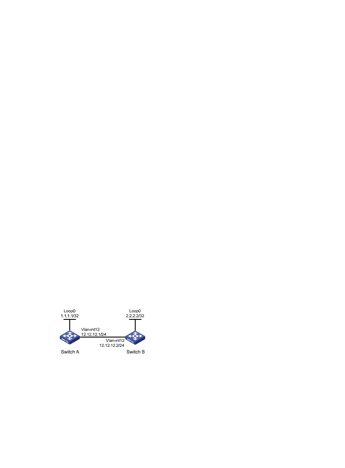
MPLS RSVP-TE and BFD cooperation configuration example
Network requirements
Run OSPF on Switch A and Switch B to ensure IP connectivity.
Enable MPLS RSVP-TE BFD on the VLAN interfaces connecting the two switches. If the link between Switch
A and Switch B fails, BFD can detect the failure quickly and inform MPLS RSVP-TE of the failure.
Figure 34 Network diagram
Configuration procedure
1. Configure basic MPLS RSVP-TE settings:
# Configure Switch A.
<SwitchA> system-view
[SwitchA] mpls lsr-id 1.1.1.1
[SwitchA] mpls
[SwitchA-mpls] mpls te
 Loading...


