216
Reply from 100.1.1.2: bytes=56 Sequence=5 ttl=255 time=80 ms
--- 100.1.1.2 ping statistics ---
5 packet(s) transmitted
5 packet(s) received
0.00% packet loss
round-trip min/avg/max = 80/126/150 ms
The output shows that CE 1 and CE 2 can ping each other.
Configuring Martini MPLS L2VPN
Network requirements
CEs are connected to PEs through VLAN interfaces.
Establish a Martini MPLS L2VPN between CE 1 and CE 2.
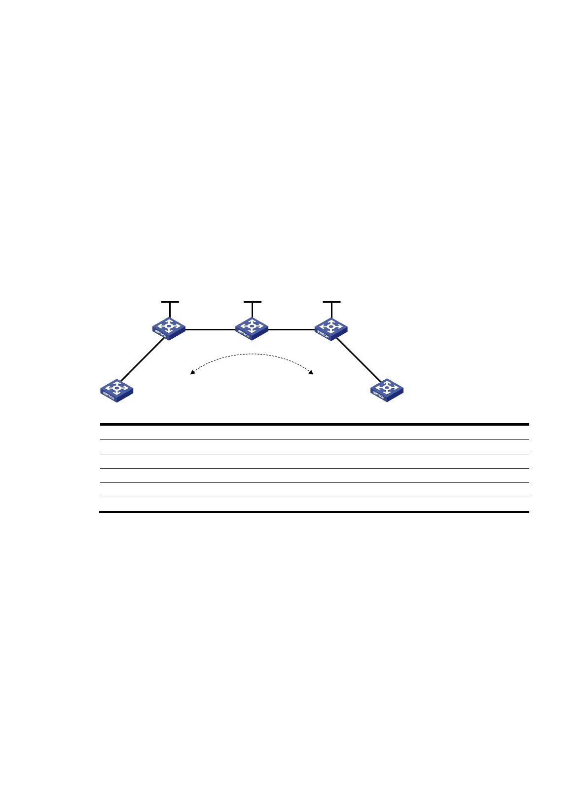
Figure 10 Network diagram
Device Interface IP address
Device
Interface
IP address
CE 1 Vlan-int10 100.1.1.1/24 CE 2 Vlan-int10 100.1.1.2/24
PE 1 Loop0 192.2.2.2/32
P
Loop0
192.4.4.4/32
Vlan-int20 10.1.1.1/24
Vlan-int20 10.1.1.2/24
PE 2 Loop0 192.3.3.3/32 Vlan-int30 10.2.2.2/24
Vlan-int30 10.2.2.1/24
Configuration procedure
1. On CE 1, configure an IP address for VLAN-interface 10 connected to PE 1.
<Sysname> system-view
[Sysname] sysname CE1
[CE1] interface vlan-interface 10
[CE1-Vlan-interface10] ip address 100.1.1.1 24
2. Configure PE 1:
# Configure the LSR ID and enable MPLS globally.
<Sysname> system-view
[Sysname] sysname PE1
[PE1] interface loopback 0
[PE1-LoopBack0] ip address 192.2.2.2 32
[PE1-LoopBack0] quit
[PE1] mpls lsr-id 192.2.2.2
CE 1
CE 2
Maitini
PE 1 PE 2P
Vlan-int20
Vlan-int20
Vlan-int30
Vlan-int30
Vlan-int10
Vlan-int10
Vlan-int10
Vlan-int10
Loop0 Loop0 Loop0
 Loading...