142
[SwitchA-Tunnel1] tunnel-protocol mpls te
[SwitchA-Tunnel1] destination 2.2.2.2
[SwitchA-Tunnel1] mpls te tunnel-id 10
[SwitchA-Tunnel1] mpls te signal-protocol rsvp-te
[SwitchA-Tunnel1] mpls te commit
[SwitchA-Tunnel1] return
5. Verify the configuration:
On Switch A, display the detailed information about the BFD session between Switch A and Switch
B.
<SwitchA> display bfd session verbose
Total Session Num: 1 Init Mode: Active
Session Working Under Ctrl Mode:
Local Discr: 21 Remote Discr: 20
Source IP: 12.12.12.1 Destination IP: 12.12.12.2
Session State: Up Interface: Vlan-interface12
Min Trans Inter: 400ms Act Trans Inter: 400ms
Min Recv Inter: 400ms Act Detect Inter: 2000ms
Running Up for: 00:00:01 Auth mode: None
Connect Type: Direct Board Num: 6
Protocol: RSVP
Diag Info: No Diagnostic
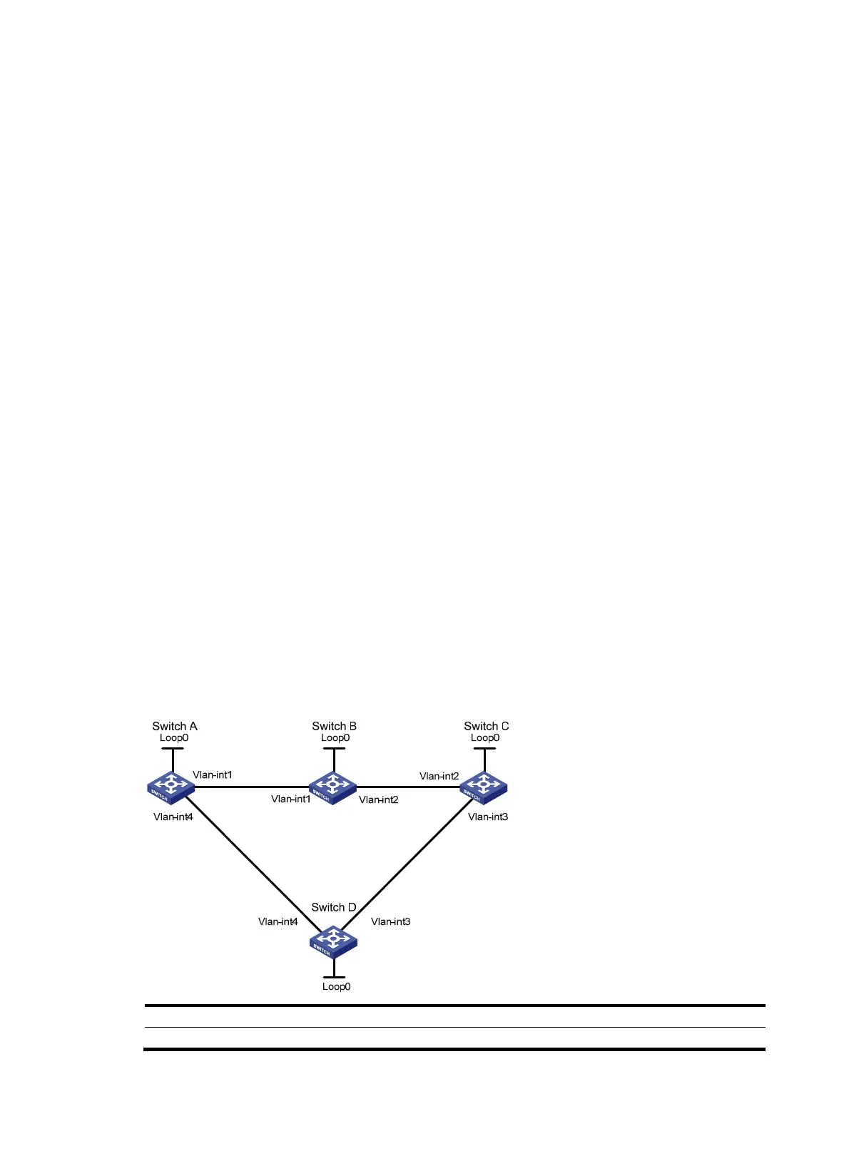
CR-LSP backup configuration example
Network requirements
Set up an MPLS TE tunnel from Switch A to Switch C. Use CR-LSP hot backup for it.
Figure 35 Network diagram
Device Interface IP address
Device
Interface
IP address
Switch A Loop0 1.1.1.9/32 Switch D Loop0 4.4.4.9/32
 Loading...