138
Car Policy : Disabled
Tunnel Group : Primary
Primary Tunnel : -
Backup Tunnel : -
Group Status : -
# Execute the display mpls te cspf tedb all command on Switch A to view information about links
in TEDB.
[SwitchA] display mpls te cspf tedb all
Maximum Node Supported: 128 Maximum Link Supported: 256
Current Total Node Number: 4 Current Total Link Number: 6
Id MPLS LSR-Id IGP Process-Id Area Link-Count
1 3.3.3.9 ISIS 1 Level-2 2
2 2.2.2.9 ISIS 1 Level-2 2
3 4.4.4.9 ISIS 1 Level-2 1
4 1.1.1.9 ISIS 1 Level-2 1
8. Direct traffic to the MPLS TE tunnel:
# Create a static route to direct traffic to the MPLS TE tunnel.
[SwitchA] ip route-static 30.1.1.2 24 tunnel 1 preference 1
# Execute the display ip routing-table command on Switch A. You can see a static route entry with
interface Tunnel1 as the outgoing interface.
RSVP-TE GR configuration example
Network requirements
Switch A, Switch B and Switch C are running IS-IS. All of them are Level-2 devices and support RSVP hello
extension.
Use RSVP-TE to create a TE tunnel from Switch A to Switch C.
Switch A, Switch B, and Switch C are RSVP-TE neighbors. Configure the RSVP-TE GR on the routers, so
each of them can provide GR helper support when another is GR restarting.
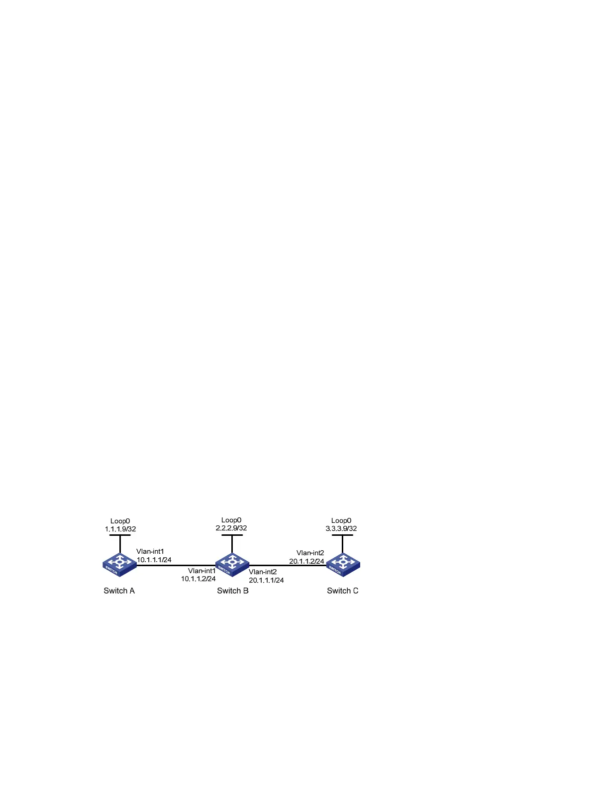
Figure 33 Network diagram
Configuration procedure
1. Configure IP addresses and masks for the interfaces according to Figure 33. (Details not shown.)
2. Enable IS-IS to advertise host routes with LSR IDs as destinations. (Details not shown.)
3. Configure basic MPLS TE, and enable RSVP-TE and RSVP hello extension:
# Configure Switch A.
<SwitchA> system-view
[SwitchA] mpls lsr-id 1.1.1.9
[SwitchA] mpls
 Loading...