■ UX-9100 1200 MHz b a n d u n i t installation
The optional UX-9100 is required to operate on the
1200 MHz frequency band.
q Remove the top and bottom covers as shown in the
diagram on page 174.
w Remove the antenna plate from the chassis on the
rear panel using a standard flat screwdriver.
R WARNING!
NEVER push on the antenna plate
using your finger to remove it. This may cause an
injury.
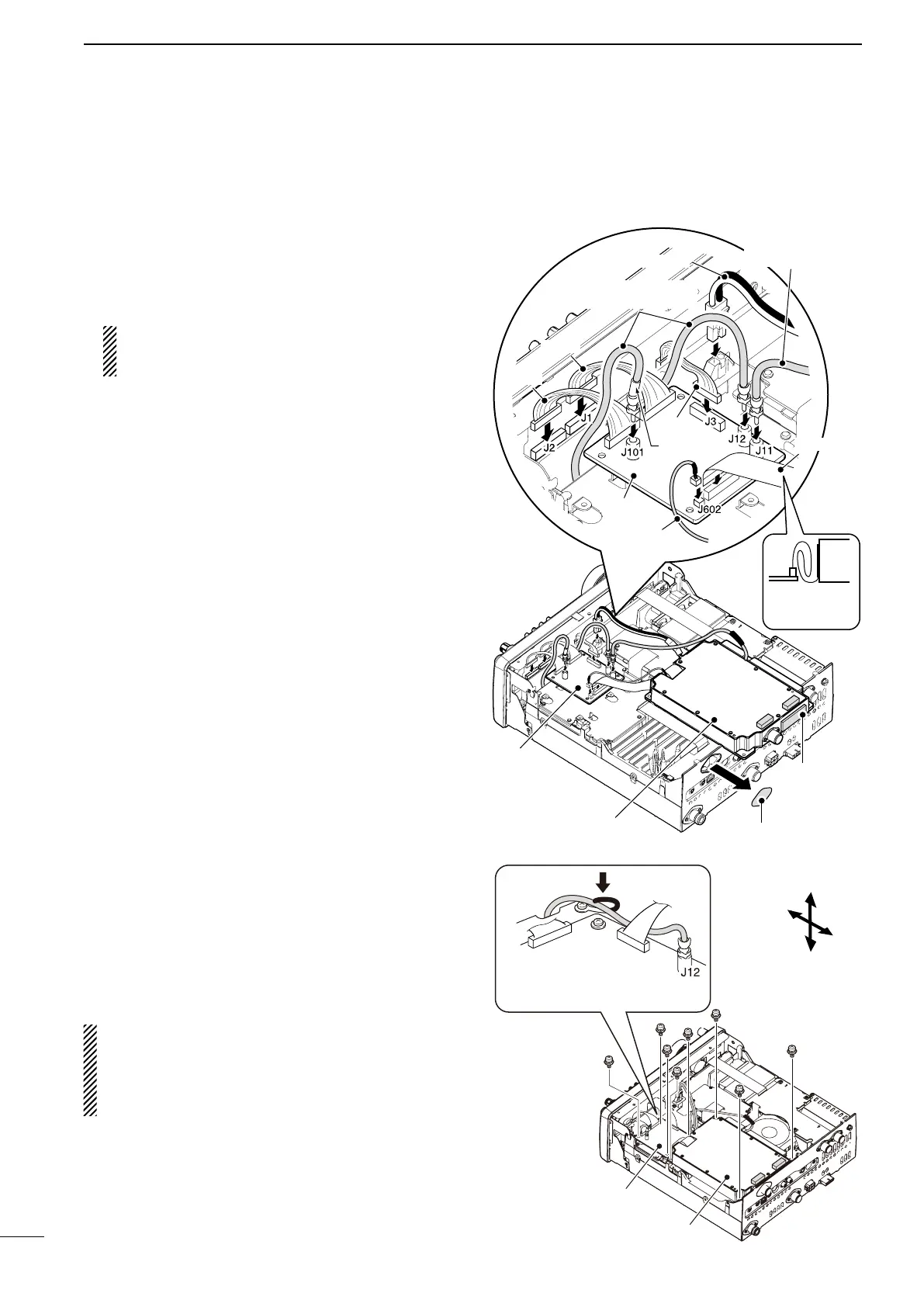
e Connect the DC power cable, coaxial cables, shield
cable and flat cable, as shown to the right.
➥ Connect the longer coaxial cable from the trans-
ceiver to J12, and the other one, with a white
mark near the connector, to J101 on the IF unit.
➥ Connect the coaxial cable from the UX-9100’s
main unit to J11 on the IF unit.
➥ Connect the shield cable from the UX-9100’s
main unit to J602 on the IF unit.
➥ Ensure the flat cable is connected to the IF unit
correctly, and not upside down.
After connecting, fold the cable, but not too
tightly, as illustrated to the right.
r Connect the 9-pin connector from the transceiver’s
front unit to J3 on the IF unit.
t Connect the 12-pin connector from the IF unit to J1,
and the 11-pin connector to J2 on the transceiver’s
front unit.
y Attach the UX-9100 and IF unit using the eight sup-
plied screws.
•MakesuretheatcableisnotpinchedwhentheUX-
9100 is installed.
u Return the top and bottom covers to their original
positions.
R WARNING! When UX-9100 is installed, the unit
continues to draw current, even when the trans-
ceiver is turned OFF. Therefore, when you don’t in-
tend to use the transceiver for a long period of time,
disconnect the transceiver’s DC power cable.
UX-9100
IF unit
Top
Bottom
Rear
Front
IF unit
DC power cable
Coaxial cable
(from the transceiver)
Flat cable
Antenna plate
Coaxial cable
(from the UX-9100)
Shield
sponge
White mark
11-pin
12-pin
9-pin
IF unit
After connect-
ing, fold the
cable like this.
Secure the coaxial cable, con-
necting to J12 on the IF unit,
by the clip, as shown here.
Shield
cable
UX-9100
 Loading...