176
16
OPTION INSTALLATION
1
2
3
4
5
6
7
8
9
10
11
12
13
14
15
16
17
18
19
20
21
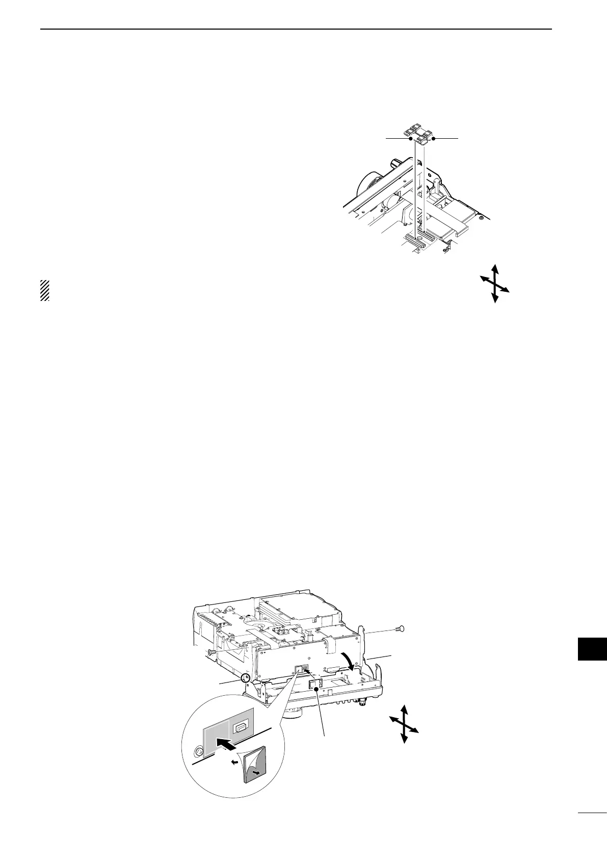
■ UT-121 digital u n i t installation
■ FL-430/FL-431
1s t if f i lt e r installation
The optional filters, FL-430 1s t if f i lt e r (6 khz) or FL-
431 1s t if f i lt e r (3 khz) provides 6 or 3 kHz filtering to
reduce interference from strong nearby signals.
q Remove the top and bottom covers as shown on
page 174.
w Install the FL-430 or FL-431 as shown to the right.
•TheconnectorsontheIC-9100aremarkedfortheap-
propriate filter.
•EnsuretheFL-430orFL-431isinstalledcorrectly.
e Return the top and bottom covers to the original po-
sitions.
After installation, a 6 kHz or 3 kHz filter width can
be used. See page 74 for details.
FL-431 (3 khz) FL-430 (6 khz)
The optional UT-121 digital u n i t is required for the DV
mode operation.
q Remove the top and bottom covers as shown on
page 174.
w Remove the upper two screws from the front panel
(q).
e Loosen the lower two screws on the front panel
(w), then slowly fold down the front panel in the
direction of the arrow (e).
r Remove the protective paper from one side of the
double sided adhesive sheet (r), then place the
sheet on the panel, as shown below. (t).
t Remove the other side of the protective paper, and
install the UT-121 as shown below (y).
y Return the front panel, top and bottom covers to
their original positions.
Top
Bottom
Rear
Front
Top
Bottom
Rear
Front
q Remove
UT-121
q Remove
w Loosen
r
w
Loosen
t
e
y
 Loading...