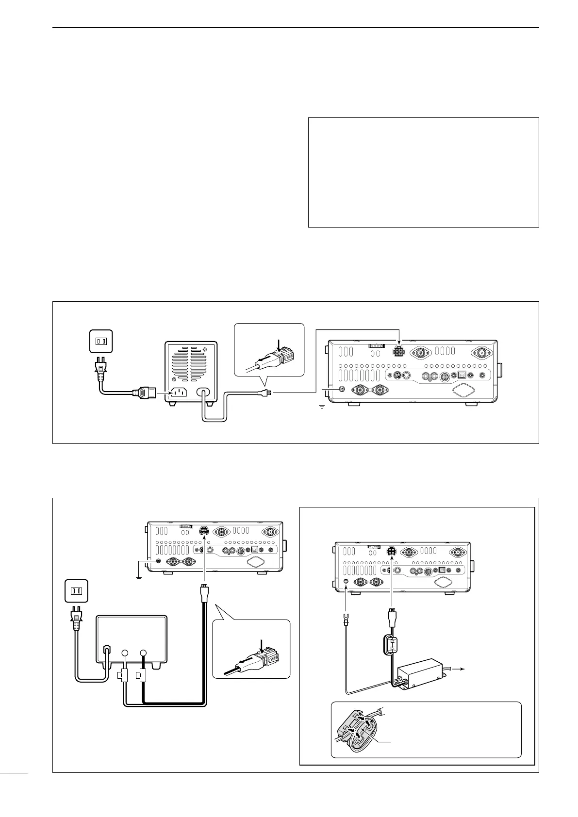
■ Power supply connections
When operating the transceiver with AC power, use a
power supply with 13.8 V DC output and a capacity of
at least 24 Amperes.
Refer to the diagrams below.
CAUTION: Before connecting the DC power
cable, check the following important items.
Make sure:
•The[POWER]switchisOFF.
•Outputvoltageofthepowersourceis12to15V
when you use a non-Icom power supply.
•DCpowercablepolarityiscorrect.
Red : Positive + terminal
Black : Negative _ terminal
27
2
INSTALLATION AND CONNECTIONS
Transceiver
Ground
PS-126
AC cable
AC outlet
To [DC 13.8V]
DC power cable
D Connecting the PS-126 DC POWER SUPPLY
D Connecting a non-Icom DC POWER SUPPLY
■ Connecting a DC power supply
Supplied DC power cable
AC cable
AC outlet
Transceiver
To [GND]
A DC power supply
13.8V;
at least 24 A
Red Black
To [DC 13.8V]
To [DC 13.8V]
For European versions
Transceiver
Ground
Connect to
power supply
To disconnect
To disconnect
When you install the ferrite
bead, make sure the cables
at the top of the loop are par-
allel to each other.
Ferrite bead
 Loading...