The access/area and link/gateway repeater call signs
must be programmed in “R1” and “R2.”
Other repeater call signs can be stored in the “RP-L”
screen (Repeater list)
(p. 88)
.
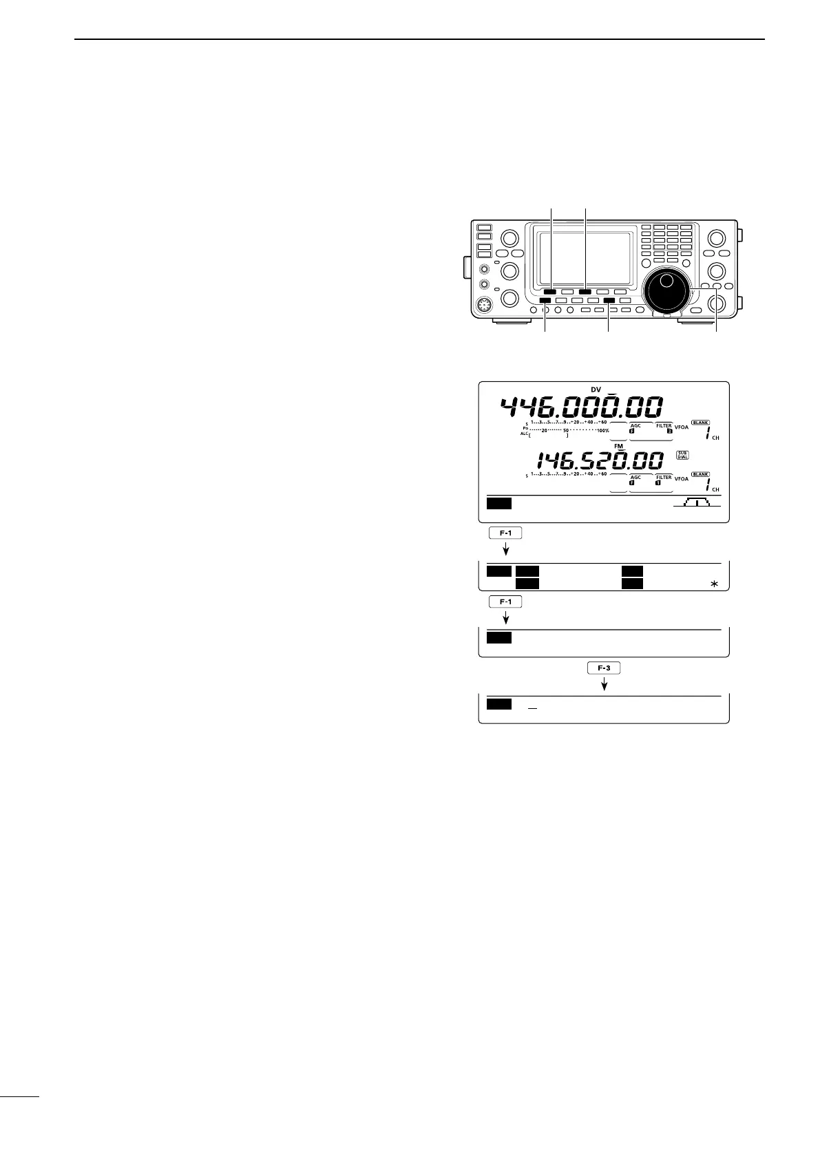
q Push [DV•DR] to select the DV mode.
w
P
ush [MENU] one or more times to display the “M3”
screen (Menu 3).
•IntheDRmode,p
ush [MENU] once or twice to select
the “D1” screen.
e
P
ush [CS](F-1) to display the “CS” screen (Call
Sign).
r
P
ush [Z](F-1) one or more times to display the “R1”
or “R2” screen (Repeater call sign setting).
t Push [EDT](F-3) to enter the call sign programming
mode.
•Acursorappearsandblinks.
y Rotate [MAIN DIAL] to select the first character to
input.
When inputting numbers, push the appropriate key-
pad key.
•Push [DEL](F-4) todelete theselectedcharacter or
number.
•Push[SPC](F-5)toinputaspace.
u Push [Ω](F-2) to move the cursor backwards, or
push [≈](F-3) to move the cursor forwards.
i Repeat steps y and u to enter a desired repeater
call sign.
•Acallsignofupto8digitscanbeset.
o Push [MENU] to store the programmed call sign.
!0 Push [MENU] again to return to the “CS” screen.
[CS]/[√] [EDT]
[MENU] [DV・DR] [MAIN DIAL]
CS UR
CQCQCQ
MY
R1
R2
NOT USE
Ú
■ Call sign programming (Continued)
D “R1” (Access/Area repeater call sign) and “R2” (Link/Gateway repeater call sign) programming
 Loading...