EasyManua.ls Logo

INVT Goodrive270 Series User Manual

INVT Goodrive270 Series
372 pages
To Next Page IconTo Next Page
To Previous Page IconTo Previous Page
Page #311 background imageLoading...
Page #311 background image
Goodrive270 series VFD for fan and pump Communication protocol
-301-
"ADDR" is "01H", indicating that the message is sent by the VFD whose address is 01H. The ADDR
information occupies one byte.
"CMD" is "03H", indicating that the message is a VFD response to the 03H command from the master
for reading data. The CMD information occupies one byte.
"Number of bytes" indicates the number of bytes between a byte (not included) and the CRC byte (not
included). The value "04" indicates that there are four bytes of data between "Number of bytes" and
"CRC LSB", that is, "MSB of data in 0004H", "LSB of data in 0004H", "MSB of data in 0005H", and
"LSB of data in 0005H".
A piece of data contains two bytes, with the MSB on the left and LSB on the right. From the response,
the data in 0004H is 1388H, and that in 0005H is 0000H.
CRC check occupies two bytes, with the LSB on the left, and MSB on the right.
9.4.2 Command code 06H, writing a word
This command is used by the master to write data to the VFD. One command can be used to write
only one piece of data. It is used to modify the parameters and running mode of the VFD.
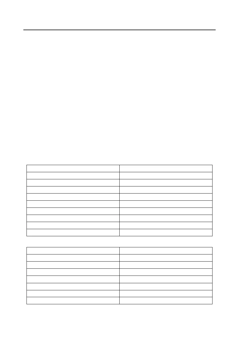
For example, if the master writes 5000 (1388H) to 0004H of the VFD whose address is 02H, the
frame structure is as follows.
RTU master command (from the master to the VFD)
START
T1-T2-T3-T4 (transmission time of 3.5 bytes)
ADDR
02H
CMD
06H
MSB of data writing address
00H
LSB of data writing address
04H
MSB of data
13H
LSB of data
88H
CRC LSB
C5H
CRC MSB
6EH
END
T1-T2-T3-T4 (transmission time of 3.5 bytes)
RTU slave response (from the VFD to the master)
START
T1-T2-T3-T4 (transmission time of 3.5 bytes)
ADDR
02H
CMD
06H
MSB of data writing address
00H
LSB of data writing address
04H
MSB of data
13H
LSB of data
88H
CRC LSB
C5H

Table of Contents

Question and Answer IconNeed help?

Do you have a question about the INVT Goodrive270 Series and is the answer not in the manual?

INVT Goodrive270 Series Specifications

General IconGeneral
Control ModeV/F control, Sensorless vector control
IP RatingIP20
Cooling MethodAir cooling
Overload Capacity150% for 60 seconds
Protection FunctionsOvercurrent, Overvoltage, Undervoltage, Overheat, Overload, Short circuit
CommunicationRS485, Modbus
ApplicationWater pump
Input Frequency50Hz/60Hz
Output Voltage0~Rated Voltage
Rated CurrentDepends on the model
Operating Temperature-10°C to +40°C
Storage Temperature-20°C to 60°C
Humidity<95% (non-condensing)
AltitudeBelow 1000m

Summary

Change History

Preface

Safety Precautions

Safety Definitions and Warnings

Defines safety terms (Danger, Warning, Note) and lists warning symbols.

General Safety Guidelines

Covers essential precautions for handling, installation, operation, and maintenance.

Quick Startup Guide

Product Inspection and Environment Checks

Details unpacking, pre-use checks, and environmental requirements for VFD installation.

Basic Commissioning Steps

Outlines fundamental steps for initial VFD setup, motor parameter configuration, and autotuning.

Product Overview

Working Principles and Specifications

Explains the VFD's basic principles, technical specifications, and features.

Model Designation and Ratings

Details the VFD model designation code and product ratings for various power outputs.

VFD Structure and Components

Illustrates the physical structure and identifies the main components of the VFD.

Installation Guidelines

Mechanical Installation

Covers environment, direction, mounting methods, clearances, and cabinet installation.

Wiring Guidelines

Details main circuit, control circuit, external keypad, and wiring protection procedures.

Basic Operation Guidelines

Keypad Operation and Display

Explains LED and LCD keypad functions, parameter display, and editing.

Core VFD Configuration and Control Modes

Covers parameter configuration, autotuning, control modes (Vector, Space Voltage), and frequency settings.

Advanced Functions and Controls

Details Simple PLC, PID control, water pump control, and protection features.

Function Parameter List

Basic and Motor Parameters (P00-P03)

Covers basic functions, motor 1 parameters, vector control, and V/F control for motor 1.

Control and I/O Parameters (P04-P07, P09-P11)

Details V/F control for motor 2, input/output terminals, human-machine interface, enhanced functions, PID, and protection.

Specific Functions and Settings (P10, P12-P28, P90-P96)

Covers Simple PLC, motor 2 parameters, communication, status, HVAC, water pump, and protection functions.

Troubleshooting Common Faults

Fault Indicators and Reset

Explains how faults are indicated and how to reset them.

Fault History and Solutions

Lists common faults, their causes, and solutions for troubleshooting.

Interference Countermeasures

Addresses interference issues with sensors, RS485, motor cables, and RCDs.

VFD Maintenance

Periodical Inspection and Cooling Fan

Outlines routine checks for VFD components and procedures for cooling fan replacement.

Capacitor and Power Cable Maintenance

Describes capacitor reforming, replacement, and power cable inspection.

Communication Protocol

Modbus RTU Communication

Details Modbus protocol, RTU frame structure, error checks, and command examples.

Expansion Card Communication

Explains wiring and functions for PROFIBUS, CAN, and PROFINET expansion cards.

Technical Data and Compliance

Derating, Specifications, and EMC

Covers derating conditions, technical specifications, EMC requirements, and application standards.

Dimension Drawings

Keypad and VFD Mounting Dimensions

Provides detailed dimensions for keypads, VFDs, and mounting brackets.

Optional Peripheral Accessories

Filters, Reactors, and Cables

Details selection guidelines for filters, reactors, and power/control cables.

Breakers, Contactors, and Other Accessories

Covers selection of breakers, contactors, and other optional accessories.

Further Information

Product Queries and Feedback

Contact information for product queries, service, and manual feedback.

Related product manuals