Goodrive270 series VFD for fan and pump Expansion card
-320-
Figure A-6 Expansion card wiring for 11–500kW VFDs
A.4 I/O cards
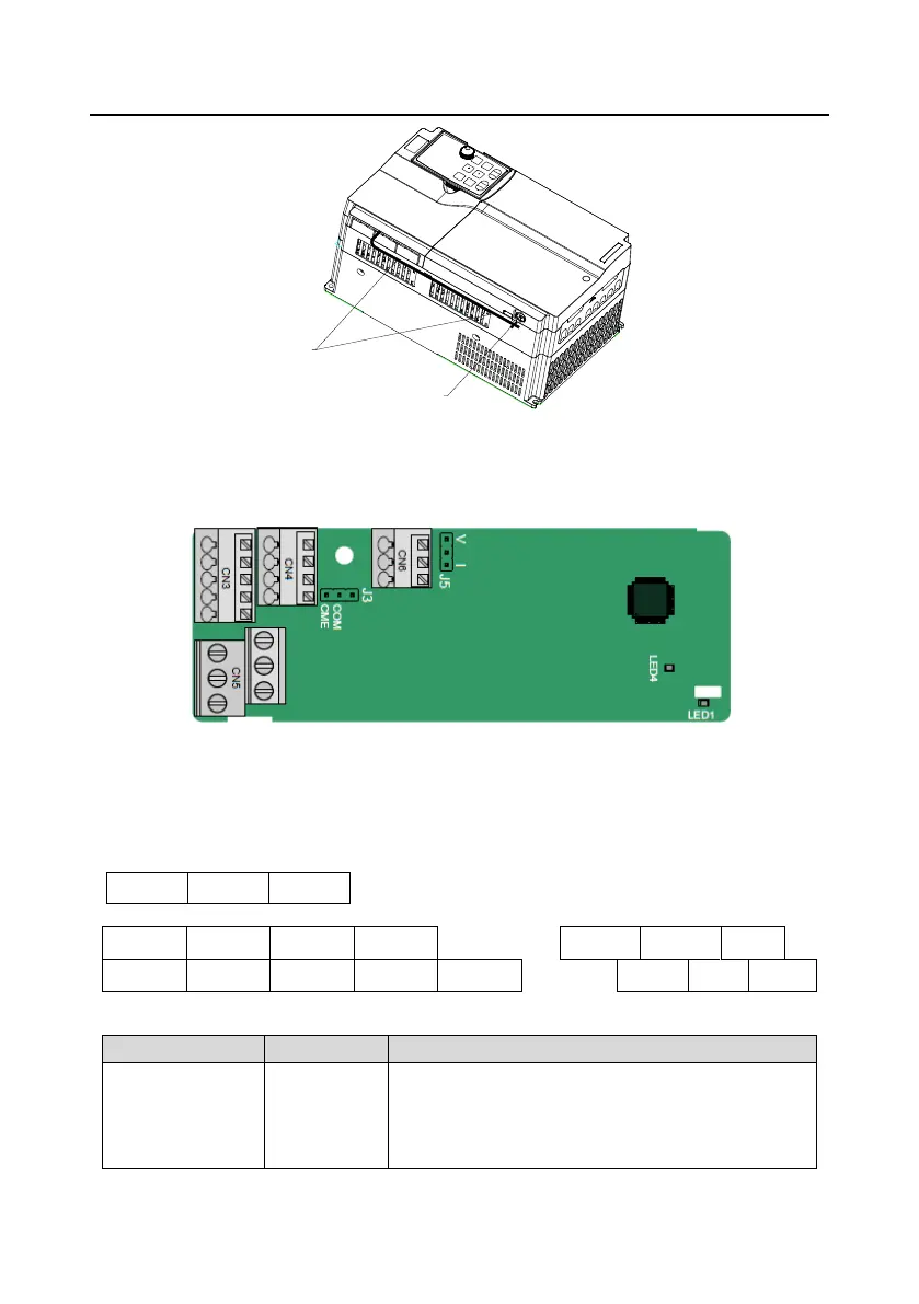
A.4.1 EC-IO501-00
CME and COM are shorted through J3 before delivery, and J5 is the jumper for selecting the output
type (voltage or current) of AO2.
The terminals are arranged as follows:
Indicator definition:
On: The expansion card is establishing a connection
with the control board.
Blinking (On: 500ms; Off: 500ms): The expansion card
is properly connected to the control board.

 Loading...