Goodrive270 series VFD for fan and pump Optional peripheral accessories
-346-
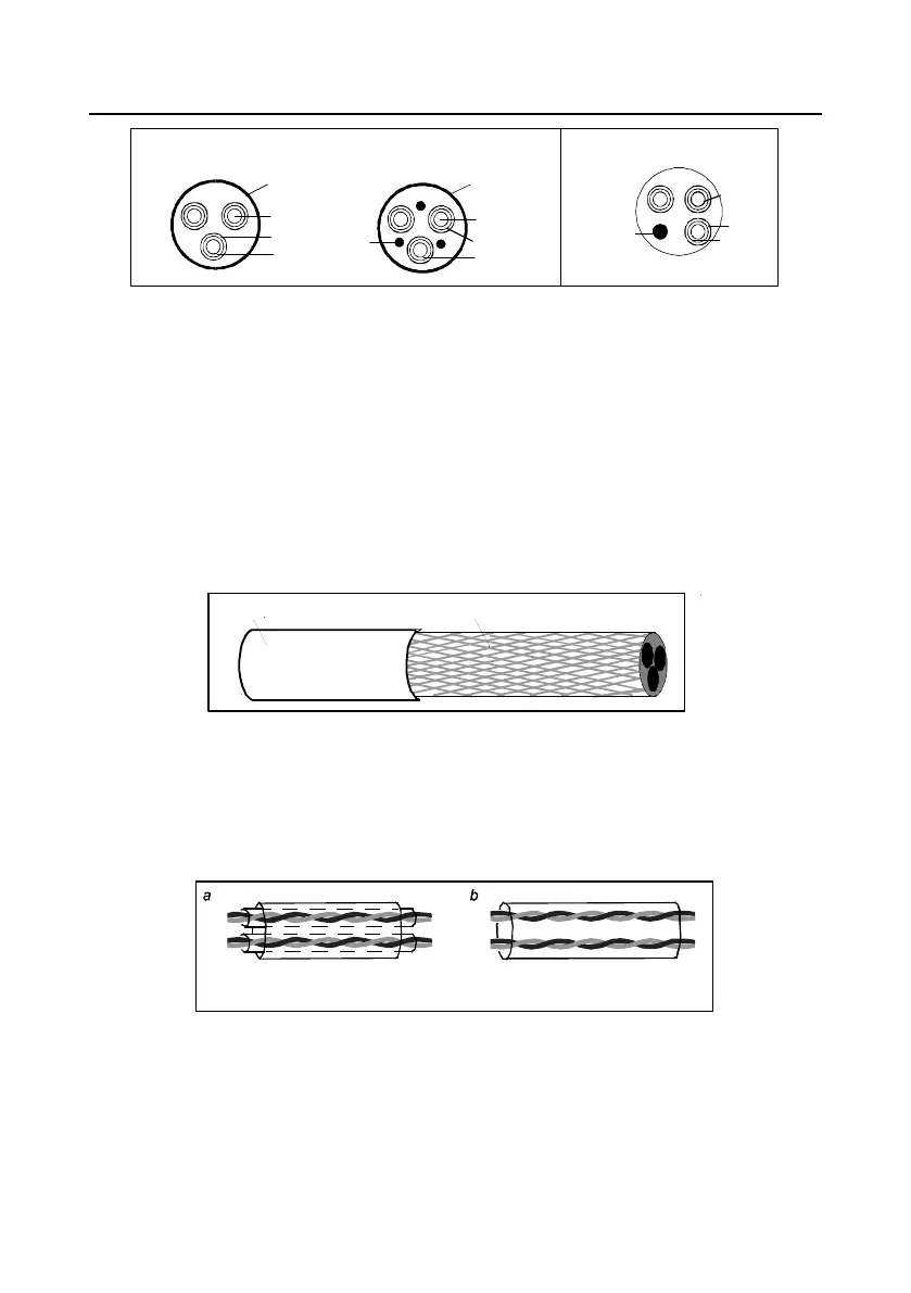
Shield layer
Jacket
Insulator
Conductor
PE
PE conductor and
shield layer
Jacket
Insulator
Conductor
Jacket
Insulator
Conductor
PE
Symmetrical shielded cable
Four-core cable
Note: If the electrical conductivity of the motor cable shield layer does not meet the requirements, a
separate PE conductor must be used.
To protect the conductors, the cross-sectional area of the shielded cables must be the same as that of
the phase conductors if the cable and conductor are made of materials of the same type. This
reduces grounding resistance, and thus improves impedance continuity.
To effectively restrict the emission and conduction of radio frequency (RF) interference, the
conductivity of the shielded cable must at least be 1/10 of the conductivity of the phase conductor.
This requirement can be well met by a copper or aluminum shield layer. Figure D-1 shows the min.
requirement on motor cables of VFD. The cable must consist of a layer of spiral-shaped copper strips.
The denser the shield layer is, the more effectively the electromagnetic interference is restricted.
Insulating layer
Shield layer
Figure D-1 Cable cross section
D.4.2 Control cables
All analog control cables and cables used for frequency input must be shielded cables. Analog signal
cables need to be double-shielded twisted-pair cables (as shown in figure a). Use one separate
shielded twisted pair for each signal. Do not use the same ground wire for different analog signals.
Cable with multiple double-shielded twisted-
pairs
Cable with multiple single-shielded
twisted-pairs
Figure D-2 Power cable arrangement
For low-voltage digital signals, double-shielded cables are recommended, but shielded or unshielded
twisted pairs (as shown in figure b) also can be used. For frequency signals, however, only shielded
cables can be used.
Relay cables need to be those with metal braided shield layers.

 Loading...