EasyManua.ls Logo

INVT Goodrive270 Series User Manual

INVT Goodrive270 Series
372 pages
To Next Page IconTo Next Page
To Previous Page IconTo Previous Page
Page #317 background imageLoading...
Page #317 background image
Goodrive270 series VFD for fan and pump Communication protocol
-307-
The following table describes the encoding rules of device codes (corresponding to the identification
code 2103H of the VFD).
8 MSBs
Meaning
8 LSBs
Meaning
0x01
GD
0x09
Goodrive35 vector VFD
0x0a
GD300 vector VFD
0xc0
GD270 vector VFD
9.4.5 Fieldbus scale
In practical applications, communication data is represented in the hexadecimal form, but
hexadecimal values cannot represent decimals. For example, 50.12 Hz cannot be represented in the
hexadecimal form. In such cases, multiply 50.12 by 100 to obtain an integer 5012, and then 50.12 can
be represented as 1394H in the hexadecimal form (5012 in the decimal form).
In the process of multiplying a non-integer by a multiple to obtain an integer, the multiple is referred to
as a fieldbus scale.
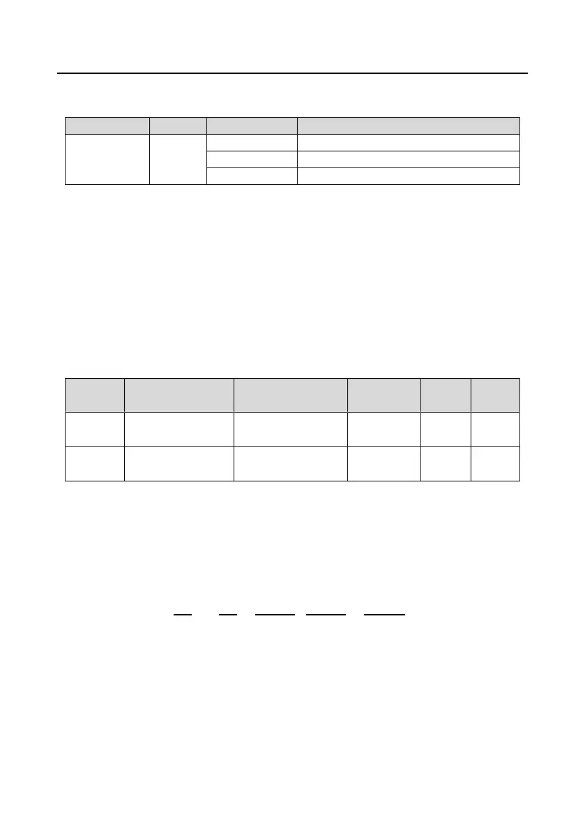
The fieldbus scale depends on the number of decimal places in the value specified in "Setting range"
or "Default". If there are n (for example, 1) decimal places in the value, the fieldbus scale m (then
m=10) is the result of 10 to the power of n. Take the following table as an example.
Function
code
Name
Description
Setting
range
Default
Modify
P01.20
Wake-up-from-sleep
delay
0.03600.0s (valid
when P01.15 is 2)
0.003600.0
0.0s
P01.21
Power-off restart
selection
0: Disable restart
1: Enable restart
01
0
The value specified in "Setting range" or "Default" contains one decimal place, and therefore the
fieldbus scale is 10. If the value received by the upper computer is 50, the value of
"Wake-up-from-sleep delay" of the VFD is 5.0 (5.0=50/10).
To set "Wake-up-from-sleep delay" to 5.0s through Modbus communication, you need first to multiply
5.0 by 10 according to the scale to obtain an integer 50, that is, 32H in the hexadecimal form, and
then send the following write command:
VFD
address
Write
command
Parameter
address
Parameter
data
CRC
01 06 01 14 00 32 49 E7
After receiving the command, the VFD converts 50 into 5.0 based on the fieldbus scale, and then sets
"Wake-up-from-sleep delay" to 5.0s.
For another example, after the upper computer sends the "Wake-up-from-sleep delay" parameter
read command, the master receives the following response from the VFD:

Table of Contents

Question and Answer IconNeed help?

Do you have a question about the INVT Goodrive270 Series and is the answer not in the manual?

INVT Goodrive270 Series Specifications

General IconGeneral
Control ModeV/F control, Sensorless vector control
IP RatingIP20
Cooling MethodAir cooling
Overload Capacity150% for 60 seconds
Protection FunctionsOvercurrent, Overvoltage, Undervoltage, Overheat, Overload, Short circuit
CommunicationRS485, Modbus
ApplicationWater pump
Input Frequency50Hz/60Hz
Output Voltage0~Rated Voltage
Rated CurrentDepends on the model
Operating Temperature-10°C to +40°C
Storage Temperature-20°C to 60°C
Humidity<95% (non-condensing)
AltitudeBelow 1000m

Summary

Change History

Preface

Safety Precautions

Safety Definitions and Warnings

Defines safety terms (Danger, Warning, Note) and lists warning symbols.

General Safety Guidelines

Covers essential precautions for handling, installation, operation, and maintenance.

Quick Startup Guide

Product Inspection and Environment Checks

Details unpacking, pre-use checks, and environmental requirements for VFD installation.

Basic Commissioning Steps

Outlines fundamental steps for initial VFD setup, motor parameter configuration, and autotuning.

Product Overview

Working Principles and Specifications

Explains the VFD's basic principles, technical specifications, and features.

Model Designation and Ratings

Details the VFD model designation code and product ratings for various power outputs.

VFD Structure and Components

Illustrates the physical structure and identifies the main components of the VFD.

Installation Guidelines

Mechanical Installation

Covers environment, direction, mounting methods, clearances, and cabinet installation.

Wiring Guidelines

Details main circuit, control circuit, external keypad, and wiring protection procedures.

Basic Operation Guidelines

Keypad Operation and Display

Explains LED and LCD keypad functions, parameter display, and editing.

Core VFD Configuration and Control Modes

Covers parameter configuration, autotuning, control modes (Vector, Space Voltage), and frequency settings.

Advanced Functions and Controls

Details Simple PLC, PID control, water pump control, and protection features.

Function Parameter List

Basic and Motor Parameters (P00-P03)

Covers basic functions, motor 1 parameters, vector control, and V/F control for motor 1.

Control and I/O Parameters (P04-P07, P09-P11)

Details V/F control for motor 2, input/output terminals, human-machine interface, enhanced functions, PID, and protection.

Specific Functions and Settings (P10, P12-P28, P90-P96)

Covers Simple PLC, motor 2 parameters, communication, status, HVAC, water pump, and protection functions.

Troubleshooting Common Faults

Fault Indicators and Reset

Explains how faults are indicated and how to reset them.

Fault History and Solutions

Lists common faults, their causes, and solutions for troubleshooting.

Interference Countermeasures

Addresses interference issues with sensors, RS485, motor cables, and RCDs.

VFD Maintenance

Periodical Inspection and Cooling Fan

Outlines routine checks for VFD components and procedures for cooling fan replacement.

Capacitor and Power Cable Maintenance

Describes capacitor reforming, replacement, and power cable inspection.

Communication Protocol

Modbus RTU Communication

Details Modbus protocol, RTU frame structure, error checks, and command examples.

Expansion Card Communication

Explains wiring and functions for PROFIBUS, CAN, and PROFINET expansion cards.

Technical Data and Compliance

Derating, Specifications, and EMC

Covers derating conditions, technical specifications, EMC requirements, and application standards.

Dimension Drawings

Keypad and VFD Mounting Dimensions

Provides detailed dimensions for keypads, VFDs, and mounting brackets.

Optional Peripheral Accessories

Filters, Reactors, and Cables

Details selection guidelines for filters, reactors, and power/control cables.

Breakers, Contactors, and Other Accessories

Covers selection of breakers, contactors, and other optional accessories.

Further Information

Product Queries and Feedback

Contact information for product queries, service, and manual feedback.

Related product manuals