Home
INVT
Water Pump
Goodrive270 Series
INVT Goodrive270 Series User Manual
5
of 1
of 1 rating
372 pages
Give review
Manual
Specs
To Next Page
To Next Page
To Previous Page
To Previous Page
Loading...
Goodrive270
series VFD
for fan and
pump
Dimension
drawings
-
336
-
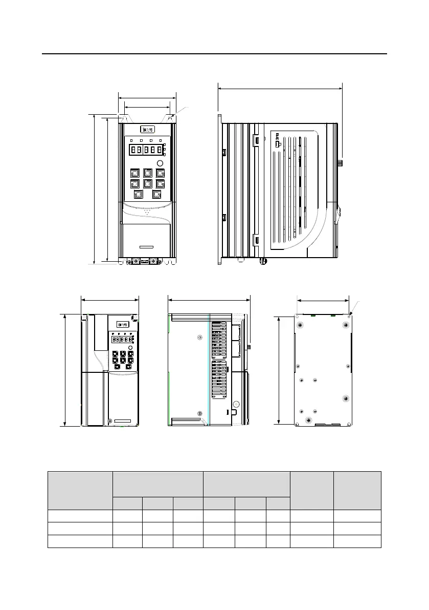
C.4 Dimensions of A
C 3PH 380V VFD models
C.4.1 W
all-moun
ting dimen
sions
H1
W1
H2
W2
d
D1
Figure C-4 1.5
–
7.5k
W VFD w
all-mounting diagra
m
W1
H1
D1
W2
H2
d
Figure C-5
11
–
4
5kW VFD
wall-moun
ting diagra
m
Table C-1 1.5
–
45k
W VFD wall-moun
ting dimension
s
VFD mode
l
Outline d
imensions
(mm)
Mounting ho
l
e
distan
ce (mm)
Hole
diameter
Fixing
screw
W1
H1
D1
H2
W2
D2
1.5
–
4k
W
89
231
193
221
70
/
ø
5
M4
5.5
–
7.5k
W
89
259
21
1.5
248
70
/
ø
6
M5
11
–
15kW
145
280
207
268
130
/
ø
6
M5
345
347
Table of Contents
Table of Contents
5
Safety Precautions
11
What this Chapter Contains
11
Safety Definition
11
Warning
11
Safety Guidelines
12
Delivery and Installation
12
Commissioning and Running
13
Maintenance and Component Replacement
14
Disposal
14
Quick Startup
15
What this Chapter Contains
15
Unpacking Inspection
15
Checking before Use
15
Environment Checking
15
Checking after Installation
16
Basic Commissioning
16
Product Overview
18
What this Chapter Contains
18
Basic Principles
18
Product Specifications
19
Product Nameplate
21
Model Designation Code
21
Product Ratings
22
Structure
23
Installation Guidelines
25
What this Chapter Contains
25
Mechanical Installation
25
Installation Environment
25
Installation Direction
26
Mounting Method
26
Installing One VFD
27
Multiple-VFD Installation
28
Vertical Installation
28
Tilted Installation
29
Cabinet Installation
29
Standard Wiring of the Main Circuit
38
Main Circuit Wiring Diagram
38
Main Circuit Terminal Diagram
39
Wiring Procedure for Main Circuit Terminals
44
Standard Wiring of the Control Circuit
45
Wiring Diagram of Basic Control Circuit
45
Input/Output Signal Connection Diagram
47
External Optional Keypad Wiring
48
Wiring Protection
49
Basic Operation Guidelines
51
What this Chapter Contains
51
Keypad Operation
51
LED Keypad (BOP-270) Display and Operation
51
Displaying Stopped-State Parameters
53
Displaying Running-State Parameters
54
Displaying Fault Alarms
54
Editing Function Codes
54
Modifying Function Codes
55
Setting a Password for the VFD
55
Viewing VFD Status
56
LCD Keypad (SOP-270) Display and Operation
56
Displaying Stopped-State Parameters
60
Displaying Running-State Parameters
60
Displaying Fault Information
61
Entering/Exiting Menus
61
Editing a Parameter List
66
Adding Parameters to the Parameter List Displayed in Stopped/Running State
67
Adding Parameters to the User Defined Parameter List
67
Editing User Defined Parameters
68
Editing Parameters in Parameter Groups
69
Monitoring States
69
Autotuning Motor Parameters
70
Backing up Parameters
70
System Settings
70
Power-On Setup Wizard
71
Basic Operation Description
73
What this Section Describes
73
Common Commissioning Procedure
73
Vector Control
77
Space Voltage Vector Control Mode
83
Torque Control
91
Motor Parameters
95
Start/Stop Control
101
Frequency Setting
105
Analog Input
110
Analog Output
112
Digital Input
116
Digital Output
125
Simple PLC
130
Multi-Step Speed Running
133
PID Control
135
Water Pump Control
140
PID Function Only for Water Supply
152
Segmented Water Pressure
153
Automatic Sleep
153
Pump Cleaning
154
Water Pipe Break Detection
156
Water Pipe Soft Padding
156
Freezing Protection
157
Condensation Protection
158
Function Parameter List
159
What this Chapter Contains
159
P00 Group-Basic Functions
160
P01 Group-Start and Stop Control
164
P02 Group--Parameters of Motor 1
171
P03 Group--Vector Control of Motor 1
174
P04 Group-V/F Control
181
P05 Group--Input Terminals
189
P06 Group-Output Terminals
197
P07 Group--Human-Machine Interface
202
P08 Group--Enhanced Functions
209
P09 Group--PID Control
217
P10 Group--Simple PLC and Multi-Step Speed Control
221
P11 Group-Protection Parameters
225
P12 Group--Parameters of Motor 2
235
P13 Group--SM Control
238
P14 Group--Serial Communication
240
P15 Group--Functions of Communication Expansion Card 1
242
P16 Group--Functions of Communication Expansion Card 2
242
P17 Group--Status Viewing
243
P19 Group--Expansion Card Status Viewing
248
P23 Group--Vector Control of Motor 2
249
P25 Group--Input Functions of Expansion I/O Card
251
P26 Group--Output Functions of Expansion I/O Card
253
P28 Group--Master/Slave Control
255
P89 Group--HVAC Status Viewing
256
P90 Group--PID1 Control
258
P91 Group--PID2 Control
262
P92 Group--Real-Time Clock and Timer (Available at Use of LCD Keypad)
266
P93 Group--Fire Control
266
P94 Group--HVAC
267
P95 Group--Segmented Water Pressure (Available at Use of LCD Keypad)
272
P96 Group--HVAC Protection
272
Troubleshooting
276
What this Chapter Contains
276
Indications of Alarms and Faults
276
Fault Reset
276
Fault History
276
Faults and Solutions
276
Other Status
283
Analysis on Common Faults
284
Motor Fails to Work
284
Motor Vibrates
285
Overvoltage
286
Undervoltage
286
Motor Overheating
287
VFD Overheating
288
Motor Stalls During ACC
289
Overcurrent
290
Countermeasures on Common Interference
290
Interference on Meter Switches and Sensors
290
Interference on RS485 Communication
292
Failure to Stop and Indicator Shimmering Due to Motor Cable Coupling
293
Leakage Current and Interference on RCD
293
Live Device Chassis
294
Maintenance
296
What this Chapter Contains
296
Periodical Inspection
296
Cooling Fan
299
Capacitor
301
Capacitor Reforming
301
Electrolytic Capacitor Replacement
302
Power Cable
302
Communication Protocol
303
What this Chapter Contains
303
Modbus Protocol Introduction
303
Application of Modbus
303
Rs485
303
RTU Mode
306
RTU Command Code and Communication Data
309
Command Code 03H, Reading N Words (Continuously up to 16 Words)
309
Command Code 06H, Writing a Word
311
Command Code 10H, Continuous Writing
312
Data Address Definition
313
Fieldbus Scale
317
Error Message Response
318
Read/Write Operation Examples
319
Common Communication Faults
324
Appendix A Expansion Card
325
Model Definition
325
Dimensions and Installation
326
Wiring
329
I/O Cards
330
Ec-Io501-00
330
Ec-Io503-00
332
Communication Cards
334
PROFIBUS-DP Communication Card (EC-TX503D)
334
CAN Multi-Protocol Communication Card (EC-TX505C)
336
PROFINET Communication Card (EC-TX509C)
337
Appendix B Technical Data
340
What this Chapter Contains
340
Derated Application
340
Capacity
340
Derating
340
Grid Specifications
341
Motor Connection Data
341
EMC Compatibility and Motor Cable Length
341
Application Standards
342
CE Marking
342
EMC Compliance Declaration
342
EMC Regulations
342
Appendix C Dimension Drawings
344
What this Chapter Contains
344
Keypad Structure
344
Structure Diagram
344
Keypad Mounting Bracket
344
VFD Structure
345
Dimensions of AC 3PH 380V VFD Models
346
Wall-Mounting Dimensions
346
Flange Mounting Dimensions
348
Floor Mounting Dimensions
351
Appendix D Optional Peripheral Accessories
354
What this Chapter Contains
354
Wiring of Peripheral Accessories
354
Power Supply
355
Cables
355
Power Cables
355
Control Cables
356
Recommended Cable Size
357
Cable Arrangement
360
Insulation Inspection
360
Breakers and Electromagnetic Contactors
361
Reactors
362
Filters
364
Input Filters
364
Output Filters
367
List of Other Optional Accessories
368
Appendix E Energy Efficiency Data
369
Appendix F Further Information
371
Product and Service Queries
371
Feedback on INVT VFD Manuals
371
Documents on the Internet
371
5
Based on 1 rating
Ask a question
Give review
Questions and Answers:
Need help?
Do you have a question about the INVT Goodrive270 Series and is the answer not in the manual?
Ask a question
INVT Goodrive270 Series Specifications
General
Brand
INVT
Model
Goodrive270 Series
Category
Water Pump
Language
English
Related product manuals
INVT GD270-030-4
336 pages
INVT GD270-090-4
336 pages

 Loading...