Goodrive270 series VFD for fan and pump Expansion card
-326-
the communication card is different from that during
the network configuration.
It blinks at the frequency of 4Hz when an error
occurs in the ASIC initialization of PROFIBUS
communication.
It is off when the diagnosis function is disabled.
On: The expansion card is powered on.
Off: The expansion card is not powered on.
For details, see the Communication Card Operation Manual.
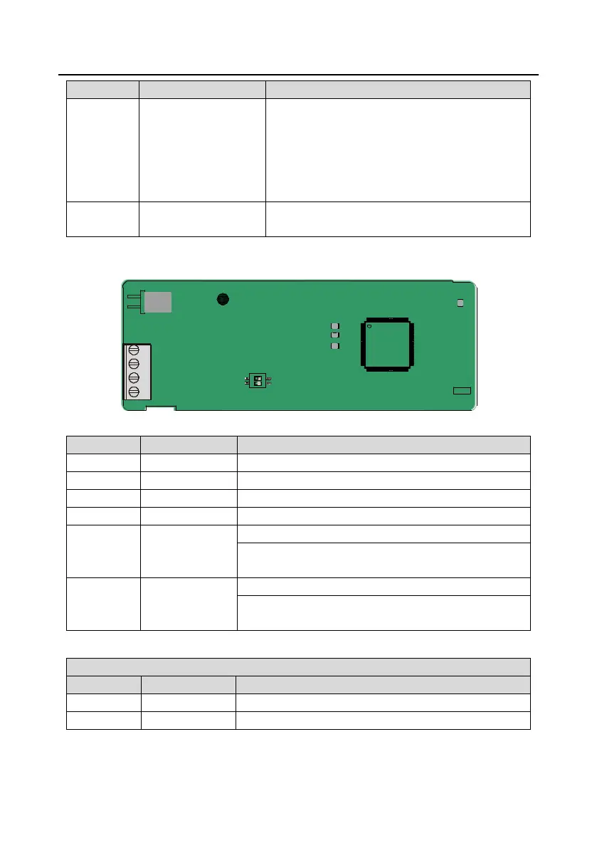
A.5.2 CAN multi-protocol communication card (EC-TX505C)
LED4
LED3
SW2
2
1
CAN
LED1
LED2
2
1
485
CN2
Table A–1 EC-TX505C communication card parts
CAN bus high level signal
485 terminal
resistor switch
RS485+ and RS485- are not connected to a terminal resistor.
RS485+ and RS485- are connected to a terminal resistor of
120Ω.
CAN terminal
resistor switch
CAN_H and CAN_L are not connected to a terminal resistor.
CAN_H and CAN_L are connected to a terminal resistor of
120Ω.
Note: Before power on, please select the protocol type by setting the switch SW2 as follows:

 Loading...