Goodrive270 series VFD for fan and pump Dimension drawings
-334-
Appendix C Dimension drawings
C.1 What this chapter contains
This chapter provides the dimension drawings of the VFD, which uses millimeter (mm) as the unit.
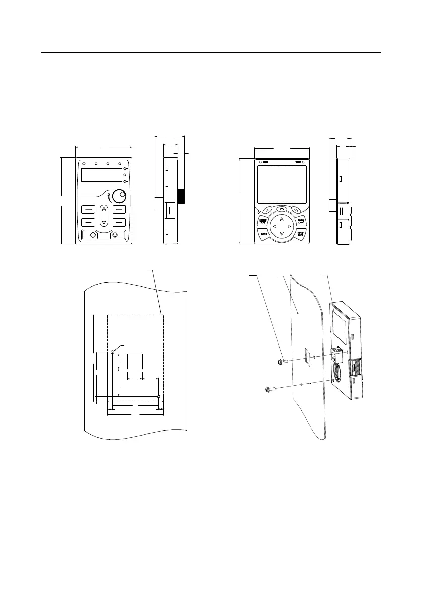
C.2 Keypad structure
C.2.1 Structure diagram
Dimension and hole sizes for mounting keypad without a bracket
109.3
71.3
28.5
16.8
2.5
RUN/TUN
E
FWD/RE
V
LOCAL/REMO
T
TRI
P
H
z
A
V
%
RPM
PRG
ESC
DATA
ENT
>
SHIFT
QUICK
JOG
RUN
STOP
RST
109.3
71
.
3
37
.
1
18
8
.
6
Keypad outline shown
in dotted line frame
2
-
ø
4
19
20
.
4
58
6
.
67
6
.
67
71
.
3
109.3
56
19
34.4
6.7
2
-
M
3
×
10
self
-
tapping
screw
Panel
Keypad
BOP-270 SOP-270
Figure C-1 Keypad structure
C.2.2 Keypad mounting bracket
Note: The external LED/LCD keypad can be mounted directly with two M3 self-tapping screws or with
a keypad bracket, as shown in the following figure.

 Loading...