Goodrive270 series VFD for fan and pump Basic operation guidelines
-59-
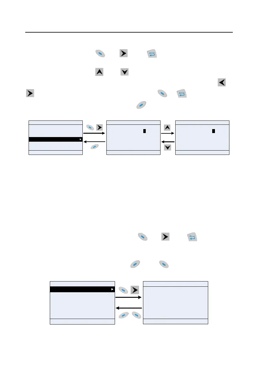
5.4.9 Editing parameters in parameter groups
You can choose Menu > Parameter groups, enter a specific function group and then a specific
function code, and then press
key, key or key to edit the parameter setting
interface. After entering edit interface, set the parameter from low bit to high bit, and the bit under
setting will be highlighted. Press key or key to increase or decrease the parameter value
(this operation is valid until the parameter value exceeds the max. value or min. value); press or
to shift the editing bit. After parameters are set, press or key to save the set
parameters and return to the previous menu; press to maintain the original parameter value
and return to the previous menu.
01: GD270
16:02:35
Fwd
Local Ready
P00.00: Speed Ctrl
P00.01: Run Cmd Channel
P00.02: Comm Cmd Channel
P00.03: Max. Output Freq
P00.04: RunFreq Up Limit
P00.05: RunFreq Low Limit
Max. Output Freq Hz
050.00
Max : 400.00
Min : 50.00
Present: 50.00
Auth: √
Default : 50.00
Max. output frequency Hz
050.01
Present: 50.00
Auth: √
EditBack
Sele
HomeBack
OK
HomeBack
OK
Max : 400.00
Min : 50.00
Default : 50.00
Figure 5-22 Editing parameters in parameter groups
In the parameter edit interface, the "Auth" field on the top right indicates whether this parameter can
be modified or not.
"√" indicates the set value of this parameter can be modified under the present state.
"×" indicates the set value of this parameter cannot be modified under the present state.
"Present" indicates the present value.
"Default" indicates the default value of this parameter.
5.4.10 Monitoring states
You can choose Menu > State monitoring > State monitoring parameter, enter a specific function
group and then a specific function code, and press
key, key or key to enter the
state monitoring interface. After entering the state monitoring interface, the actual parameter value will
be displayed in real time, this value is the actually detected value which cannot be modified.
In the state monitoring interface, you can press key or key to return to the previous
menu.
Set Freq Hz
50.00
Max : 400.00
Min : 0.0
01: GD270
16:02:35
Fwd
Local Ready
Default : 0.0
16:02:35
P17.00: Set Freq
P17.01: OutpFreq
P17.02: Ramp Ref Freq
P17.03: Outp Volt
P17.04: Outp Cur
P17.05: Motor Speed
Fwd Local Ready 01: GD270
Back Add Sele Back Home OK
Figure 5-23 State monitoring interface

 Loading...