Goodrive270 series VFD for fan and pump Installation guidelines
-37-
which can be set through function codes
• S4 and Y1 share the output terminal. The selection is made
through J10.
In addition to digital input functions, the terminal can also act as a high frequency
pulse input channel.
Max. input frequency: 50kHz
Duty ratio: 30%–70%
4.4.2 Input/output signal connection diagram
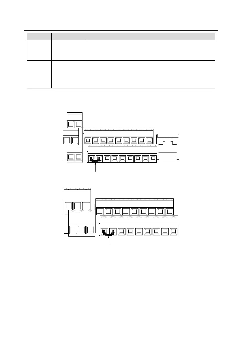
You can select the NPN/PNP mode and internal/external power through the U-type short connector.
NPN internal mode is adopted by default. NPN internal mode is adopted by default.
RO1A
RO2A
RO1B
RO2B
RO1C
RO2C
S1 S2 S3
S4/Y1
HDIA
AO1
AI1
AI2
+10V
+24V
PW
COM
COM
AO0
GND
485+
485-
PE
U-shaped jumper
between +24V and PW
Figure 4-36 Position of U-type short connector of 3PH 380V 1.5–7.5kW VFD models
AI1
+24V
AO1
HDIA
S4/Y1
S3
S2
S1
PW
COM
COM
AO0
GND
RO1A
RO1B
RO1C
RO2A
RO2B
RO2C
485+
485-
PE
+10V
AI2
U-shaped jumper between
+24V and PW
Figure 4-37 Position of U-type short connector of 3PH 380V 11–500kW VFD models
If the input signal comes from the NPN transistor, set the U-shaped jumper between +24V and PW
based on the power used according to the following figure.

 Loading...