Goodrive270 series VFD for fan and pump Installation guidelines
-38-
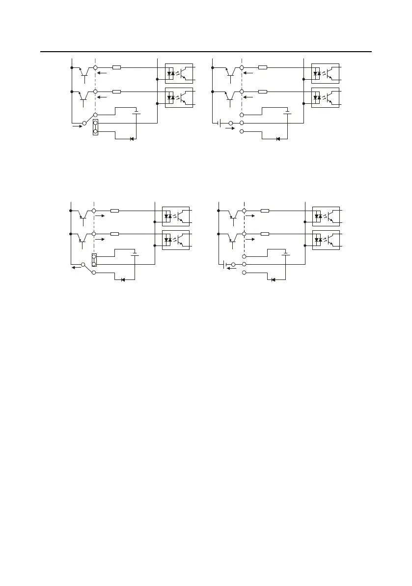
S1
S2
COM
PW
+
24V
COM
+ 24V
Internal power(NPN mode)
S1
S2
COM
PW
+ 24V
COM
+
24V
External power(NPN mode)
+ 24V
Figure 4-38 NPN mode
If the input signal comes from the PNP transistor, set the U-shaped jumper based on the power used
according to Figure 4-39.
S1
S2
COM
PW
+ 24V
COM
+ 24V
External power(PNP mode)
S1
S2
COM
PW
+ 24V
COM
+ 24V
Internal power(PNP mode)
Figure 4-39 PNP mode
4.5 External optional keypad wiring
The VFD supports optional LED keypad (BOP-270) and LCD keypad (SOP-270). Note the following
when externally connecting an optional keypad:
The 1.5–22kW models use the film keypad design, which allows you to connect an external
optional LED or LCD keypad to the electrical cabinet through the keypad interface A. With
connection to an external keypad, the VFD support display and operation on both the local film
keypad and external keypad.
The 30kW and higher models are configured with independent keypads as standard parts.
Before delivery, the local keypad of any of these models has been connected to the keypad
interface B by default. If you want to move the keypad from the local to the electrical cabinet, to
ease wiring, disconnect the default keypad wiring and connect the keypad through the keypad
interface A. Keypad interfaces A and B cannot be connected at the same time. Otherwise, the
keypad fails to operate or display properly.

 Loading...