HYDRAULIC SYSTEM
M6040, M7040Narrow, WSM
N8-S3
3. CHECKING AND ADJUSTING
[1] POSITION AND DRAFT CONTROL LINKAGE
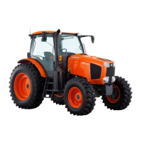
Adjusting Position Control Rod and Draft Control Rod
1. Be sure to adjust the position control rod (1) length "L1" and
draft control rod (4) length "L2".
• Each draft control lever and position control lever should
contact with lever guide lowest position when operate the
position lever 1 (3) and draft lever 1 (2) to end of direction
"a".
If not, adjust the position control rod (1) length "L1" and/or
draft control rod (4) length "L2".
[ROPS Model]
[CABIN Model]
9Y1210220HYS0003US0
Position control rod
length "L1"
Factory specification
Approx.
180 mm
7.09 in.
Draft control rod length
"L2"
Factory specification
Approx.
170 mm
6.69 in.
Position control rod
length "L1"
Factory specification
Approx.
262 mm
10.31 in.
Draft control rod length
"L2"
Factory specification
Approx.
235 mm
9.25 in.
(1) Position Control Rod
(2) Draft Lever 1
(3) Position Lever 1
(4) Draft Control Rod
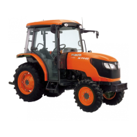
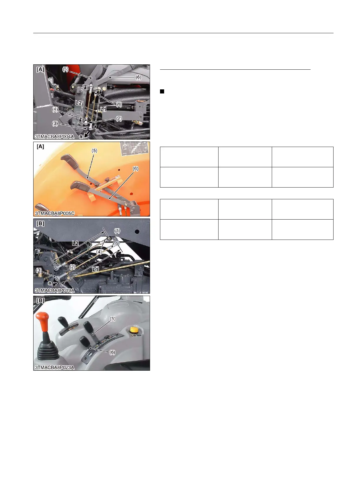
(5) Position Control Lever
(6) Draft Control Lever
[A] ROPS Model
[B] CABIN Model
L1 : Length of Position Control Rod
L2 : Length of Draft Control Rod
a : Direction for Lower
 Loading...