ELECTRICAL SYSTEM
M6040, M7040Narrow, WSM
N9-S16
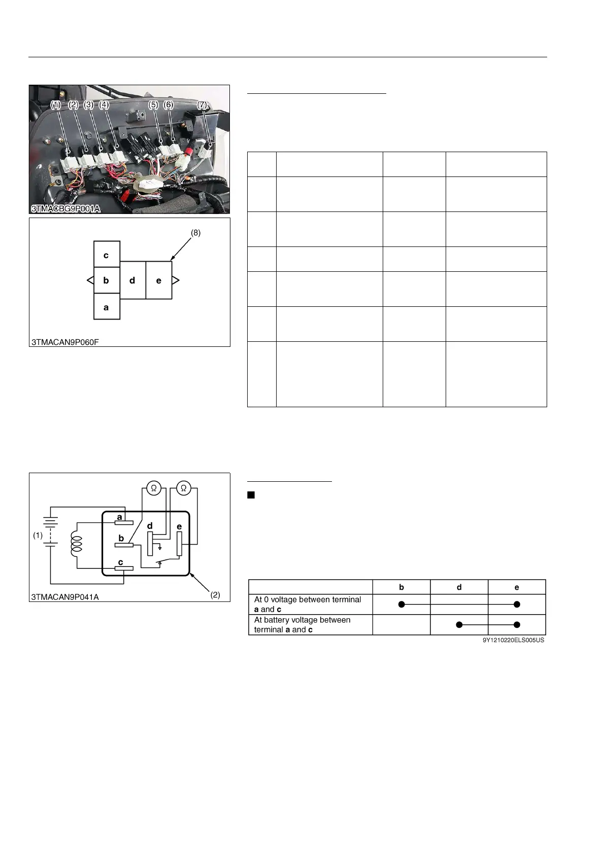
(2) ROPS Model
Checking Connector Voltage
1. Measure the voltage with a voltmeter across the battery terminal
and chassis as table below.
2. If the voltage differs from the battery voltage, the wiring harness
or fuse is faulty.
9Y1210220ELS0025US0
Functional Check
• The relays described here are used same ones so that
these are interchangeable.
1. Apply battery voltage across the terminals a and c, and check
for continuity across the terminals d and e.
2. If continuity is not established across terminals d and e, replace
it.
9Y1210220ELS0026US0
(1)
Engine stop relay (main
switch at ON position)
Terminal c –
Chassis
Approx. battery voltage
(2)
PTO safety relay (main
switch at ON position and
PTO lever OFF position)
Terminal c –
Chassis
Approx. battery voltage
(3)
Work light relay (front)
(main switch at OFF
position)
Terminal e –
Chassis
Approx. battery voltage
(4)
Key stop relay (main
switch at OFF position)
Terminal e –
Chassis
Approx. battery voltage
(5)
Head light relay (low)
(main switch at OFF
position)
Terminal d –
Chassis
Approx. battery voltage
(6)
Head light relay (high)
(main switch at OFF
position)
Terminal d –
Chassis
Approx. battery voltage
(7)
4WD / Bi-speed turn relay
(main switch at ON, 4WD /
Bi-speed turn switch at
bi-speed position and
turning angle inspection
switch at ON)
Terminal c –
Chassis
Approx. battery voltage
(1) Engine Stop Relay
(2) PTO Safety Relay
(3) Work Light Relay (Front)
(4) Key Stop Relay
(5) Head Light Relay (Low)
(6) Head Light Relay (High)
(7) 4WD / Bi-speed Turn Relay
(8) Connector (Wire Harness)
(1) Battery (2) Connector (Relay)

 Loading...