ELECTRICAL SYSTEM
M6040, M7040Narrow, WSM
N9-S17
(3) CABIN Model
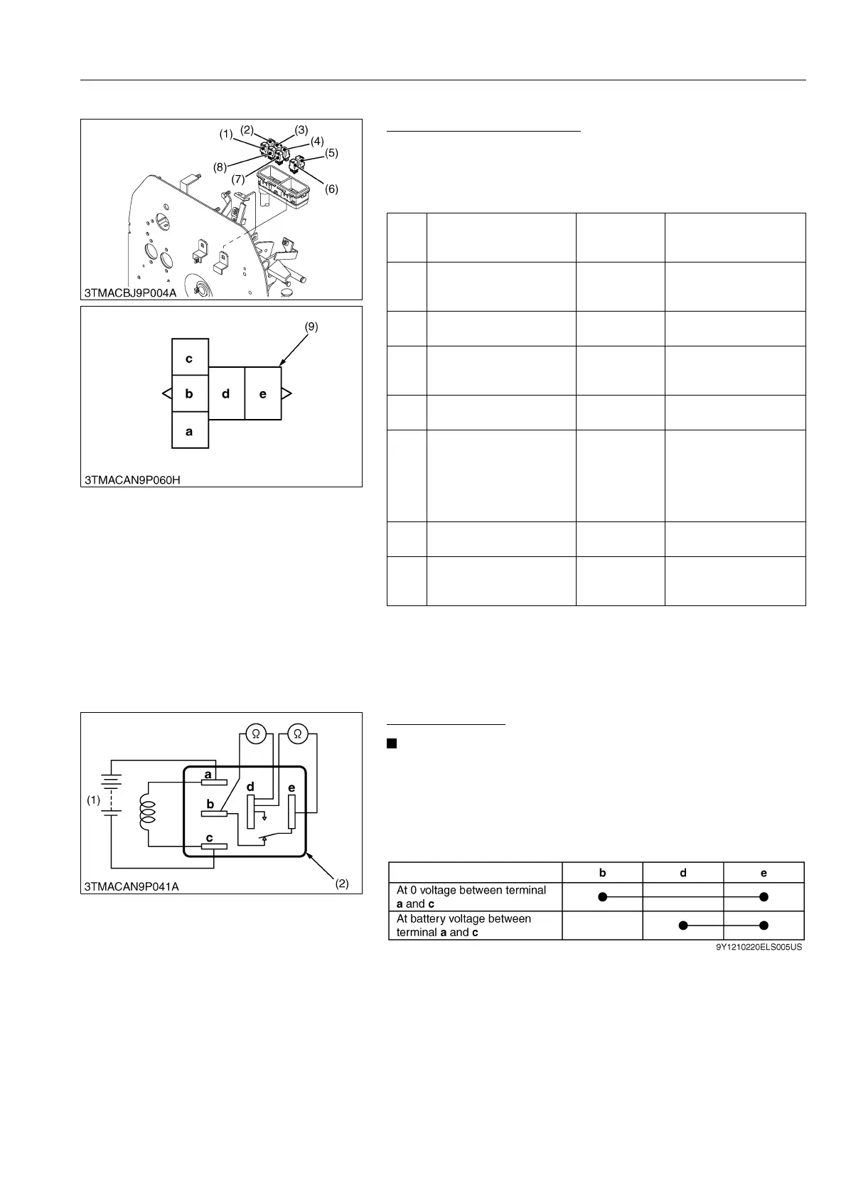
Checking Connector Voltage
1. Measure the voltage with a voltmeter across the battery terminal
and chassis as table below.
2. If the voltage differs from the battery voltage, the wiring harness
or fuse is faulty.
9Y1210220ELS0027US0
Functional Check
• The relays described here are used same ones so that
these are interchangeable.
1. Apply battery voltage across the terminals a and c, and check
for continuity across the terminals d and e.
2. If continuity is not established across terminals d and e, replace
it.
9Y1210220ELS0028US0
(1)
Defogger rear window
Relay (main switch at OFF
position)
Terminal d –
Chassis
Approx. battery voltage
(2)
Defogger quarter window
relay (main switch at OFF
position)
Terminal d –
Chassis
Approx. battery voltage
(3)
Key stop relay (main
switch at OFF position)
Terminal e –
Chassis
Approx. battery voltage
(4)
Work light relay (front)
(main switch at OFF
position)
Terminal e –
Chassis
Approx. battery voltage
(5)
Engine stop relay (main
switch at ON position)
Terminal c –
Chassis
Approx. battery voltage
(6)
4WD / Bi-speed turn relay
(main switch at ON, 4WD /
Bi-speed turn switch at
bi-speed position and
turning angle inspection
switch at ON)
Terminal c –
Chassis
Approx. battery voltage
(7)
Work light relay (Main
switch at OFF position)
Terminal e –
Chassis
Approx. battery voltage
(8)
PTO safety relay (main
switch at ON position and
PTO lever OFF position)
Terminal c –
Chassis
Approx. battery voltage
(1) Defogger Rear Window Relay
(2) Defogger Quarter Window Relay
(3) Key Stop Relay
(4) Work Light Relay (Front)
(5) Engine Stop Relay
(6) 4WD / Bi-speed Turn Relay
(7) Work Light Relay (Front)
(8) PTO Safety Relay
(9) Connector (Wire Harness)
(1) Battery (2) Connector (Relay)

 Loading...