ELECTRICAL SYSTEM
M6040, M7040Narrow, WSM
N9-S9
(2) Checking Meter Panel, PTO/Hour Meter Select Switch and Traveling
Speed Select Switch
• For checking of electric circuit, use the circuit tester.
• As for the checking of sensors and switches, do the following order; check the battery, fuse and
grounding line first, check by the test function of meter panel next, and check the connectors of panel or
related electronic switch or sensor. If any defect is found there, check individual sensors or switches to
see whether the defect exists at the sensor and switch side or at the wire harness side.
• When any defect is not found for sensors, switches and harness, replace meter panel with new one.
• When connecting or disconnecting the connector for the purpose of checking, be sure to turn OFF the
main switch before hand. Moreover, pay attention not to allow the terminal to come in contact with other
terminal or chassis while checking.
• When applying the test pin of the tester to the connector terminals, use care not to damage to the
connector terminal.
9Y1210220ELS0013US0
Checking Connector Voltage, Sensor Resistance and Switch
Continuity
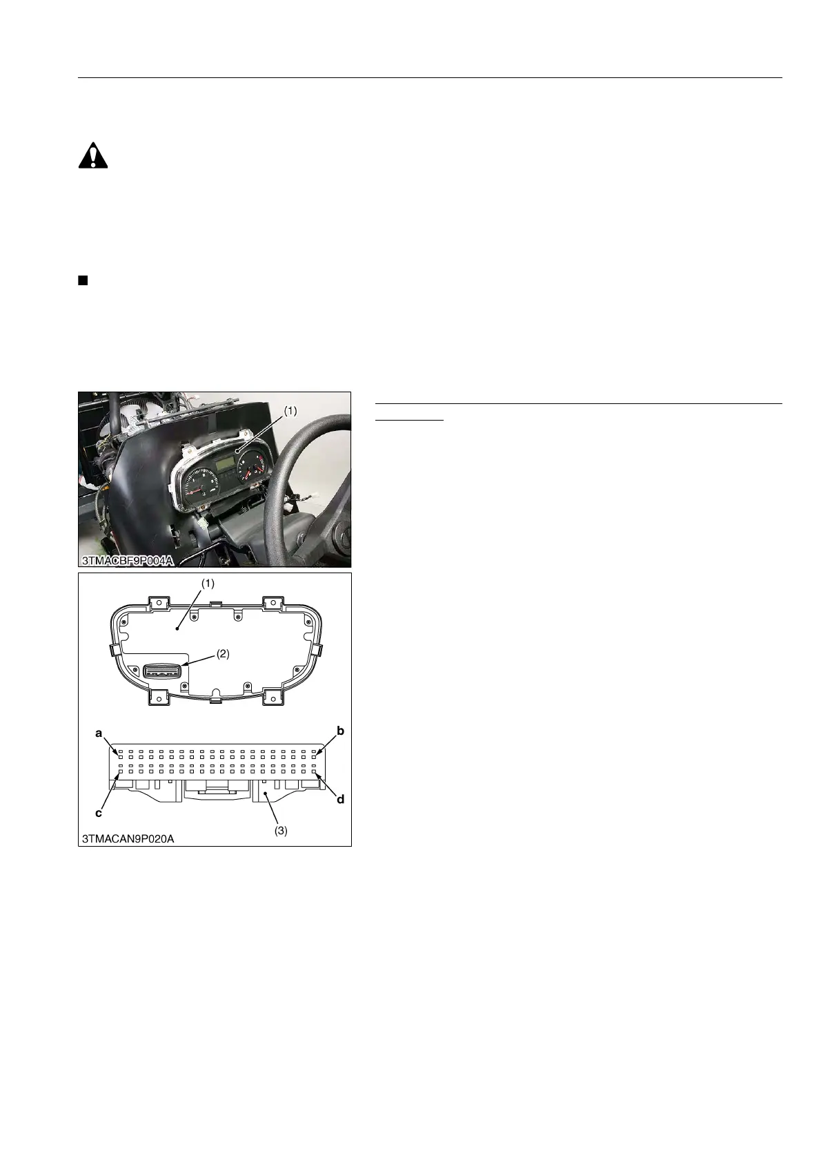
1. Remove the panel cover, refer to "[1] CLUTCH PEDAL" at "2.
CLUTCH" section (for ROPS model).
2. Remove the meter panel (1).
3. DIsconnect the 40P connector (2) from the meter panel.
4. Check the main voltage (battery voltage) first and check the
connector voltage, sensor resistance or switch continuity which
related for defective indication of meter panel as table below.
(When reassembling)
• Tighten the meter panel mounting screw evenly.
9Y1210220ELS0014US0
(1) Meter Panel
(2) 40P Connector Meter Panel Side
(3) 40P Connector Wire Harness Side
a : Terminal 1 (T1)
b : Terminal 20 (T20)
c : Terminal 21 (T21)
d : Terminal 40 (T40)

 Loading...