CABIN
M6040, M7040Narrow, WSM
N10-S3
3. CHECKING, DISASSEMBLING AND SERVICING
[1] CHECKING AND ADJUSTING
(1) Control Panel (Blower Switch, A/C Switch, Mode Control Dial and
Temperature Control Dial)
Blower Switch Connector Voltage
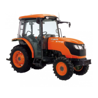
1. Draw out the control panel (1).
2. Disconnect the 6P connector (2) from blower switch.
3. Turn the main switch to "ON" position.
4. Measure the voltage with a voltmeter across the connector
terminal a and terminal b.
5. If the voltage differs from the battery voltage, the wiring harness,
A/C relay, fuse or main switch is faulty.
9Y1210220CAS0003US0
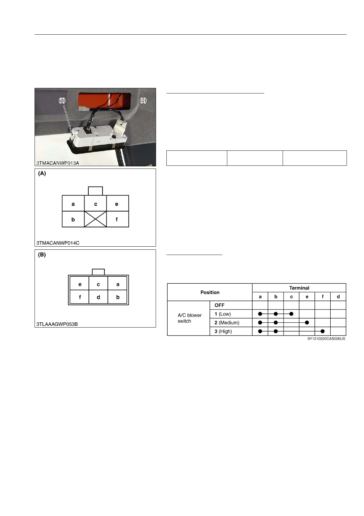
Blower Switch Test
1. Check the continuity through the switch with an ohmmeter.
2. If the continuity specified below are not indicated, the switch is
faulty.
9Y1210220CAS0004US0
Voltage
Termi n al a –
Termi n al b
Approx. battery voltage
(1) Control Panel
(2) 6P Connector
(A) 6P Connector
(Wire Harness Side)
(B) 6P Connector
(Blower Switch Side)
 Loading...