CABIN
M6040, M7040Narrow, WSM
N10-M2
[2] SYSTEM CONTROL
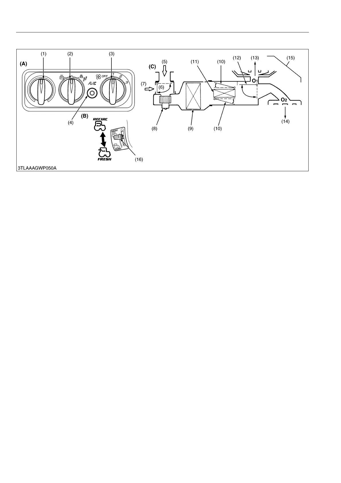
1) Selection of recirculated air (7) or fresh air (5) is done with door D1.
RECIRC
By setting the air selection lever (16) in rear control panel to RECIRC position, door D1 (6) shuts the flesh air inlet
port. Air inside the cabin is recirculated.
FRESH
By moving the air selection lever (16) to FRESH position, door D1 (6) opens the flesh air inlet port. Outside air
comes into cabin.
2) Temperature control of outlet air is done with door D2.
COOL
By setting the temperature control dial (1) in control panel to COOL position, door D2 (10) is moved to close water
valve. The air flows to door D3 (12) side without passing the heater core.
WARM
By moving the temperature lever to WARM position door D2 (10) is moved to open water valve. The air flows to
door D3 (12) side passing through the heater core.
3) Outlet air flow is controlled by door D3.
Moving the mode switch (2) opens and shuts door D3 (12) and establishes the air passage according to the lever
position.
DEF + FACE
By moving the mode lever to DEF + FACE position, the door D3 (12) is moved to establish the air passages to
outlets O
1
and O
2
. Air comes out from both outlets.
DEF
Moving the mode lever to DEF position, door D3 is moved to set up the air passage to outlet O
1
. Air comes out
from outlet O
1
.
9Y1210220CAM0002US0
(1) Temperature Control Dial
(2) Mode Switch
(3) Blow Switch
(4) Air Conditioner Switch with
Indicator Light
(5) Fresh Air
(6) Air Intake Door D1
(7) Recirculated Air
(8) Blower
(9) Evaporator
(10) Temperature Door D2
(Air Mixed Door)
(11) Heater
(12) Air Outlet Door D3
(Mode Door)
(13) DEFOGGER
(14) FACE
(15) DEF and FACE
(16) Air Selection Lever
(A) Control Plate
(B) Air Selection Lever
(C) Block Diagram of Air Flow
Passage
O
1
: Front air outlet
O
2
: Side air outlet
 Loading...