ELECTRICAL SYSTEM
M6040, M7040Narrow, WSM
N9-S15
[4] RELAYS
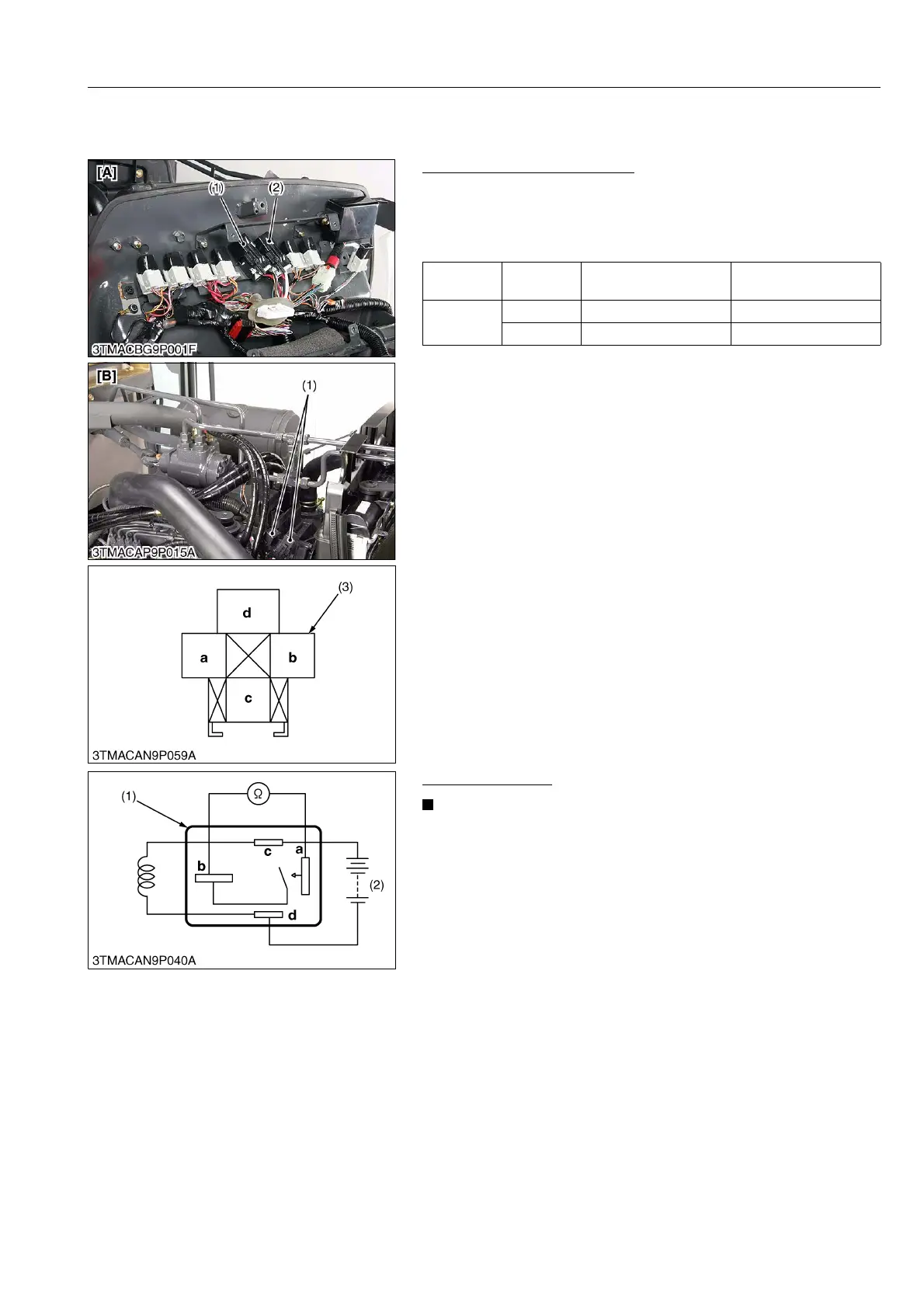
(1) Starter Relay and Heater Relay
Checking Connector Voltage
1. Measure the voltage with a voltmeter across the battery terminal
and chassis as table below.
2. If the voltage differs from the battery voltage, the wiring harness
or fuse is faulty.
9Y1210220ELS0023US0
Functional Check
• The relays described here are used same ones so that
these are interchangeable.
1. Apply battery voltage across the terminals c and d, and check
for continuity across the terminals a and b.
2. If continuity is not established across the terminals a and b,
replace it.
9Y1210220ELS0024US0
Starter
relay
ROPS and
CABIN
Termi n al d – Chassis Approx. battery voltage
Heater
relay
ROPS Terminal c – Chassis Approx. battery voltage
CABIN Terminal d – Chassis Approx. battery voltage
(1) Starter Relay
(2) Heater Relay
(3) Connector (Wire Harness)
[A] ROPS Model
[B] CABIN Model
(1) Connector (Relay) (2) Battery

 Loading...