CABIN
M6040, M7040Narrow, WSM
N10-S8
(7) Pressure Switch
Pressure Switch
1) HI Pressure Side
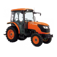
1. Connect the manifold gauge (5) to compressor as following
procedure.
Close the HI and LO pressure valves (3), (4) of manifold gauge
tightly, and connect the charging hoses (2), (1) (red and blue) to
the respective compressor service valves. (Refer to "[1]
HANDLING OF SERVICE TOOLS" at "10. CABIN" section.)
• Be sure to drive out the air in the charging hoses at the
manifold gauge connection end by utilizing the refrigerant
pressure in the refrigerant cycle.
2. Start the engine and set at approx. 1500 min
-1
(rpm). Turn on
the A/C switch, then set the blower switch to HI position.
3. Raise pressure on the HI pressure side of the refrigerant cycle
by covering the condenser front with a corrugated carboard, and
the pressure switch is activated and the compressor magnetic
clutch is turned off. At this time, read the HI pressure gauge of
the manifold gauge. If this pressure reading differs largely with
the setting pressure, replace the pressure switch with a new
one.
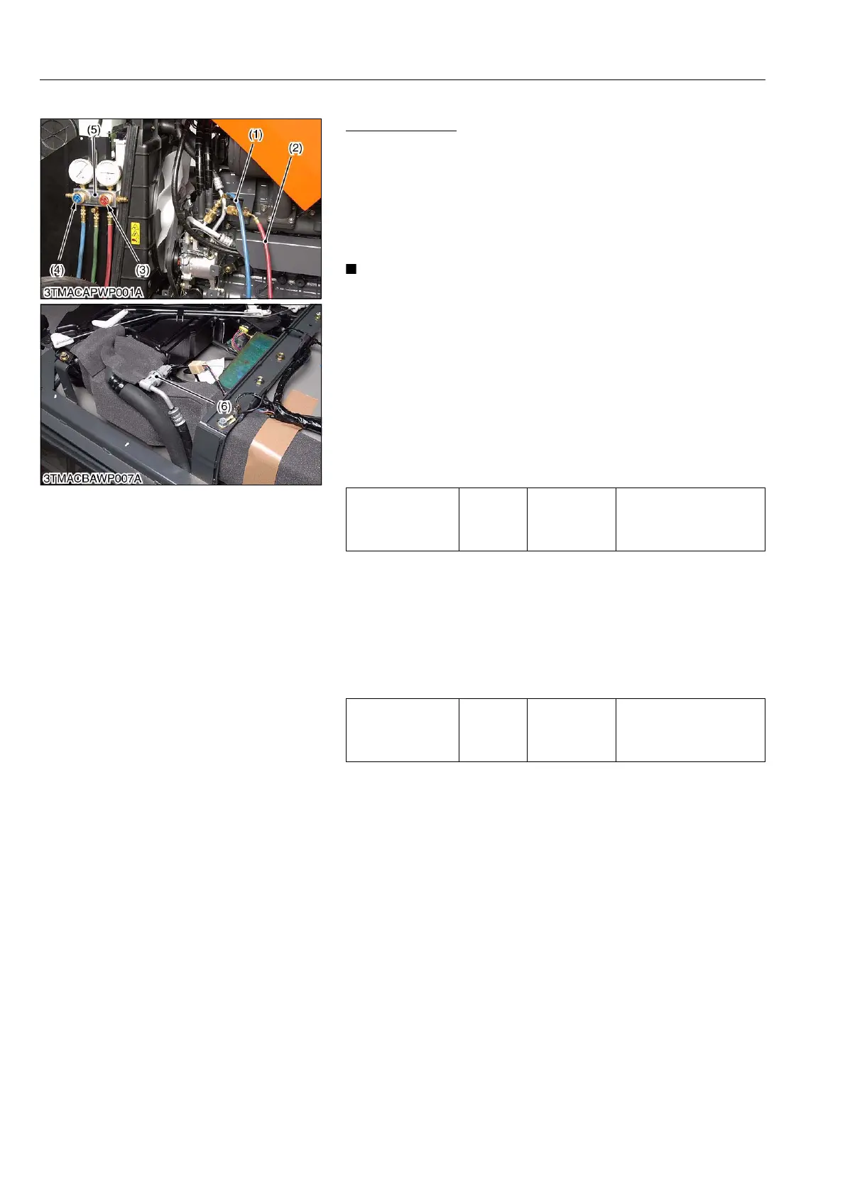
2) LO Pressure Side
1. Disconnect 2P connector of pressure switch (6).
2. Measure the resistance with an ohmmeter across the connector
terminals.
3. If 0 ohm is not indicated at normal condition, there is no
refrigerant in the refrigerating cycle because gas leaks or
pressure switch is defective.
(Reference)
• The resistance of pressure switch is 0 ohm in normal condition,
but it becomes infinity if the pressure is out of factory spec..
Because the pressure switch starts to work.
9Y1210220CAS0014US0
Setting pressure
Factory
specifica-
tion
Pressure
switch OFF
More than approx.
3.14 MPa
32 kgf/cm
2
455 psi
Setting pressure
Factory
specifica-
tion
Pressure
switch OFF
Less than approx.
0.196 MPa
2.0 kgf/cm
2
28.4 psi
(1) Charging Hose (Blue)
(2) Charging Hose (Red)
(3) HI (High Pressure Side) Charging
Valve
(4) LO (Low Pressure Side) Charging
Valve
(5) Manifold Gauge
(6) Pressure Switch
 Loading...